Field Service Bulletin 5
HyPro2000 — HT2000 TORCH UPGRADE
If you are installing a new control board skip to step 4.
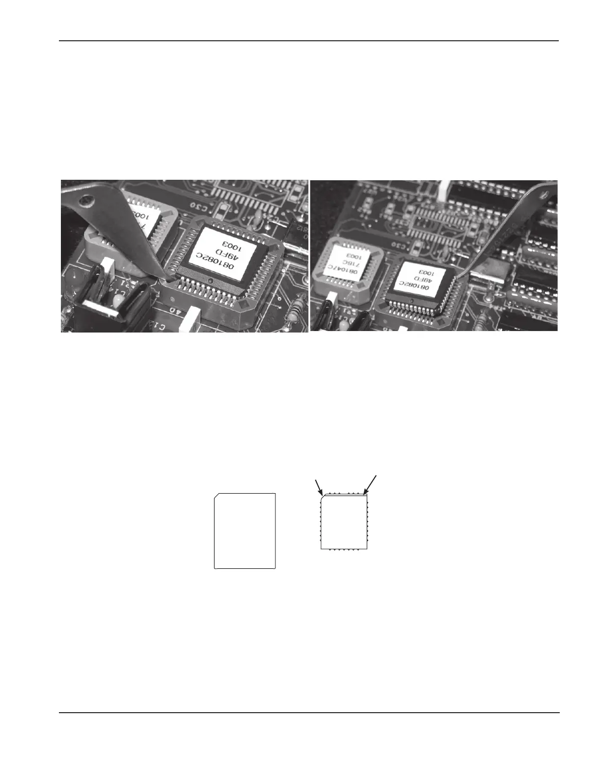
3. Remove and discard the old chip by using the tool included in this kit. See pictures below.
a. Place the straight end of the chip removal tool under one corner of the chip. Only 2 opposite corners will
accept the tool.
b. Carefully pry each of the 2 corners alternately until the chip is removed. Prying the chip out from only one
corner can damage the chip receptacle.
4. Chose the appropriate chip from fi rmware kit 228571 (located in the main kit box), and install it in the chip
receptacle on the control board.
Use the chip labeled 081192 for an RHF system.
Use the chip labeled 081194 for an LHF system.
Note: NOTE: The chip must be oriented correctly before installation. DO NOT use the orientation of the label to
orient the chip to the chip receptacle. There is a bevel on one edge of each chip and one corner is
angled (see fi gure below).
5. If you are installing a new control board see Installation of the new control board on the next page.
If you have installed the new chip on an existing control board see step 2 of Installation of the new control
board on the next page, before you replace the 2 front panels of the power supply and continue to torch and
quick-disconnect installation.
Bevel
Angled corner
Firmware Chip
Chip receptacle
on PCB