Wring Illustration
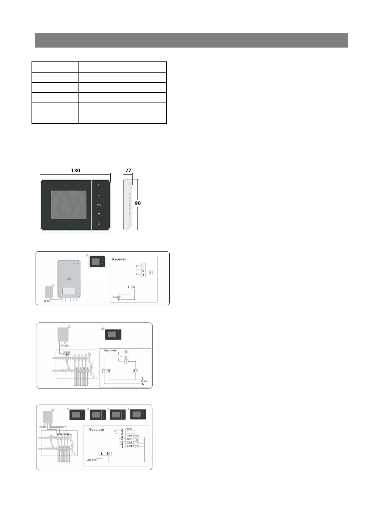
1、Wiring Terminals
Wiring Terminal Remarks
N AC Neutral
L AC Live
1 NO (Normally-Open point)
2 COM (Public terminal of relay)
3 NC (Normally-Closed point)
2、Symbol Illustration
B:Wall Mounted Gas Boiler
U:Water Pump, Thermal Actuator or electromagnetic valve 3 control picture:
Fig.2: Dimensional Diagram – Length, Width, Thickness, Installing Size
Fig.3: Control of Water Pump, Thermal Actuator or electromagnetic valve for RF model
Fig.4: Control of Wall-mounted Boiler for HY01RFB mode
Fig.5: Control of Under Floor Heating with Wireless 4-channel for MRF mod