EasyManua.ls Logo

Hyster E60XL - User Manual

Hyster E60XL
21 pages
Print Icon
To Next Page IconTo Next Page
Loading...
Hyster C108 (E40XL, E50XL, E55XL, E60XL) Electric Forklift
Question and Answer IconNeed help?

Do you have a question about the Hyster E60XL and is the answer not in the manual?

Summary

Steering System for Electric Lift Trucks

Safety Precautions for Maintenance and Repair

Safety Warning and Caution Indicators

Explains the meaning of WARNING and CAUTION symbols and text.

General Steering System Information

Steering System Description

Overview of hydraulic steering system and its operation.

Steering Wheel and Column Assembly Repair

Procedures for repairing the steering wheel and column.

Power Steering Motor and Pump

Information on the power steering motor and pump assembly.

Hydraulic Steering Motor

Details on the hydraulic steering motor.

Steering System Troubleshooting

Guidance for diagnosing and resolving steering system issues.

General Steering System Operation Details

Steering System Types Description

Details the differences between Power Steering and Power Steering with On-Demand.

Steering System Hydraulic Operation

Steering System Operation Details

Describes how the steering wheel rotation controls hydraulic oil flow.

Steering System Hydraulic Schematic

Diagram of the steering system's hydraulic connections and flow.

Steering Wheel and Column Assembly Repair

Remove Steering Wheel and Column Components

Step-by-step guide for disassembling the steering wheel and column.

Remove Steering Column Assembly

Instructions for removing the entire steering column from the truck.

Install Steering Column Assembly Components

Steps for installing the steering column assembly components.

Connect Hydraulic Hoses

Ensures correct connection of hydraulic hoses to prevent issues.

Power Steering Motor and Pump

Power Steering Motor and Pump Description

Provides general information on the location and operation of the motor/pump assembly.

Disassemble Power Steering Motor and Pump

Procedures for removing and disassembling the motor and pump assembly.

Remove Motor, Pump, and Bracket Assembly

Removing the motor, pump, and mounting bracket as a unit.

Overview

This document is a service and repair manual for the Hyster C108 (E40XL, E50XL, E55XL, E60XL) Electric Forklift, specifically focusing on its steering system. The manual, identified by PART NO. 897450 and 1600 SRM 485, covers various models of Hyster electric lift trucks, including:

  • A1.00-1.50XL (A20-30XL) [A203]
  • J2.00-3.00XL (J40-60XL) [B168]
  • E1.25-1.75XL (E25-35XL) [C114]
  • E2.00-3.00XL (E40-60XL) [C108]
  • E3.50-5.50XL (E70-120XL, E70-120XL3) [C098]
  • E1.50-2.00XMS (E25-40XMS, E25-40XM2S) [D114]
  • E2.00-3.20XM (E45-65XM, E45-65XM2) [F108]
  • J2.00-3.20XM (J40-60XM, J40-60XM2) [A216]
  • N30XMH, N30XM2H [A210, C210]

The primary function of the device, as detailed in the manual, is to provide a comprehensive guide for the service, repair, and maintenance of the electric power steering system in these Hyster lift trucks. It outlines two main steering systems: Power Steering and Power Steering with On-Demand.

Function Description:

The steering system is a hydraulic system that lacks a mechanical connection between the steering wheel and the Master Drive Unit (MDU) or steering axle. Instead, control is achieved through a hydraulic circuit. An electric motor drives a hydraulic pump. For the system to operate, the key switch must be ON, and the seat switch must be closed. In Power Steering systems, the pump motor runs continuously after the initial start-up sequence. For On-Demand steering systems, the pump motor only operates when the steering wheel is turned.

When the steering wheel is rotated, hydraulic oil is directed to the steering motor (for units with an MDU) or the steering cylinder (for units with a steering axle). This oil flow controls the direction and degree of turn. On MDU-equipped units, a hydraulic motor with a sprocket rotates the MDU via a steering chain. On steering axle units, the steering cylinder moves the steering linkage to steer the wheels. Hydraulic oil then returns from the motor or cylinder to the steering control unit and finally to the hydraulic tank.

A notable feature of the On-Demand system is a delay (approximately 1 to 5 seconds, depending on the model) between the last steering wheel rotation and the system de-energizing. This delay ensures the system remains active during straight travel when the operator is not actively turning the wheel. In the event of a steering pump malfunction, a check valve allows the steering control unit to still operate the hydraulic motor or steering cylinder, enabling steering, albeit with increased effort.

Important Technical Specifications:

The manual implicitly covers various components, including:

  • Steering Wheel and Column Assembly: This includes the steering shaft, horn switch, key switch, and, for On-Demand systems, an optical encoder and activator. The optical encoder, driven by a gear on the steering shaft, sends signals to the activator, which completes the battery negative circuit to energize the steering pump motor.
  • Steering Control Unit: This unit acts as a rotary valve, directing hydraulic oil flow and volume to control steering direction and turn degree.
  • Power Steering Motor and Pump: This assembly, typically located under the floor plate or within the battery compartment (depending on the model), consists of an electric motor and a hydraulic pump. For units with a steering axle, a pressure switch in the hydraulic circuit energizes the pump motor contactor when system pressure exceeds 2.07 kPa (0.3 psi), allowing continuous operation even without steering wheel movement.
  • Hydraulic Hoses: These connect the steering control unit to the steering motor or cylinder, and to the hydraulic tank.
  • Master Drive Unit (MDU) or Steering Axle: The MDU is used in three-wheel units, while a steering axle is used in four-wheel units.
  • Electrical System: Involves battery connectors, wiring harnesses, and switches (key, seat, direction).

Usage Features:

  • Adjustable Steering Column: The steering column can be adjusted for different operators and must be raised to the UP position for battery removal/installation.
  • On-Demand Steering: This feature optimizes energy consumption by activating the steering pump motor only when the steering wheel is turned, with a built-in delay to maintain operation during straight travel.
  • Emergency Steering Capability: A check valve allows manual steering even if the power steering pump fails, though with increased effort.

Maintenance Features:

The manual provides detailed procedures for:

  • Removal and Installation of Components: Covers the steering wheel and column assembly, power steering motor and pump, and hydraulic steering motor.
  • Disassembly and Assembly: Instructions for breaking down and reassembling various parts, including the power steering pump motor.
  • Cleaning and Inspection: Guidelines for cleaning components and inspecting them for wear or damage.
  • Seal Replacement: Specific instructions for replacing seals, particularly the oil seal in the power steering pump motor.
  • Electrical Checks: Procedures for checking the optical encoder and activator circuits.
  • Hydraulic Checks: Includes steering system air removal and steering pressure checks.
  • Steering Chain Tension Check: Applicable to units with an MDU.
  • Troubleshooting: A section dedicated to diagnosing and resolving issues within the steering system.
  • Safety Precautions: Emphasizes disconnecting the battery, using lifting mechanisms for heavy parts, wearing safety glasses, using correct blocks, maintaining a clean work area, using correct and clean tools, and always using HYSTER APPROVED replacement parts. It also highlights the importance of following WARNING (immediate death or injury) and CAUTION (property damage) notes.

The manual is structured to guide technicians through each repair process, often advising to perform only necessary steps rather than a full overhaul. It also references other SRM (Service Repair Manual) sections for related components like the Master Drive Unit, Steering Axle, Steering Control Unit, Hydraulic System, Instrument Cluster, Instrument Panel Indicators and Senders, Electrical System, Periodic Maintenance, and DC Motor Maintenance, indicating a modular approach to service documentation.
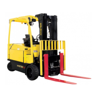
Hyster E60XL Specifications

General IconGeneral
ModelE60XL
Load Capacity6000 lbs
Power SourceElectric
Lift Height189 inches
Battery Voltage48V
Tire TypePneumatic
Travel Speed10 mph
CategoryForklift

Related product manuals