Do you have a question about the HYT TM-600 and is the answer not in the manual?
Details precautions for operating the radio in vehicles and with specific fuel types.
Provides recommendations for safe and proper mobile radio installation in vehicles.
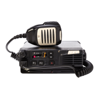
Describes the function of each control and indicator on the radio's front panel.
Describes the function of each connector and port on the radio's rear panel.
Lists the adjustable parameters and their corresponding displays in tuning mode.
Provides a step-by-step guide for entering and navigating tuning mode.
Details the RF amplifier and bandpass filter circuit for signal conditioning.
Explains the function of the first mixer in generating the intermediate frequency.
Describes the amplification and filtering of intermediate frequency signals.
Explains the circuit responsible for amplifying the audio output signal.
Details the squelch circuit for controlling audio output based on signal strength.
Explains the components and operation of the radio's transmitter section.
Describes the microphone input and modulation stages of the transmitter.
Explains the power amplification stages for transmission.
Details the Automatic Power Control circuit for maintaining constant output power.
Explains the circuit for external data signal modulation.
Describes the Phase-Locked Loop circuit for frequency generation.
Describes the Central Processing Unit and its role in controlling radio functions.
Details the power supply circuitry and voltage regulation.
Explains the watchdog timer and reset functionality for system recovery.
Describes the components and operation of the radio's display system.