This document provides a quick reference guide for the Hytera HR106X Digital Repeater, covering its product overview, internal parts, basic operations, and maintenance.
Function Description
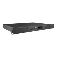
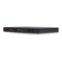
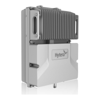
The Hytera HR106X Digital Repeater is designed to extend the range and improve the reliability of radio communication systems. It functions as a base station that receives radio signals and retransmits them, effectively expanding the coverage area for two-way radio users. The repeater supports both digital and analog modes, allowing for flexible integration into existing communication infrastructures. It can operate in various environments, including those with frequent thunderstorms, by utilizing an external lightning protection module. The device is equipped with multiple interfaces for power, network connectivity, and accessory connections, making it adaptable to different deployment scenarios.
Important Technical Specifications
Power Supply:
- AC Power: 100-240 V
- DC Power: 13.6V±15% (for PA Module)
Interfaces (Front Panel - Advanced Version):
- TX Antenna Connector: 1
- Monitor/Tuning Interface: 1
- Accessory Connector: 1
- RX Antenna Connector: 1
- Ethernet Interface 1 & 2: 2 (Ethernet Interface 1 and Ethernet Interface 2 must serve as LAN port and WAN port respectively)
- USB Connector: 1
- DC Power Inlet: 1
- AC Power Inlet: 1
- AC Power Switch: 1
- Ground Screw: 1
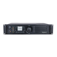
Interfaces (Front Panel - Basic Version):
- Air Inlet for PA: 1
- Volume/Channel + Key: 1
- Volume/Channel – Key: 1
- Seven-segment Display: 1
- Alarm Indicator: 1
- Timeslot B RX Indicator: 1
- Timeslot B TX Indicator: 1
- Timeslot A RX Indicator: 1
- Timeslot A TX Indicator: 1
- Analog Mode Indicator: 1
- Digital Mode Indicator: 1
- Audio/Programming Interface: 1
- Air Inlet for Power Supply: 1
Interfaces (Rear Panel - Basic Version):
- TX Antenna Connector: 1
- Monitor/Tuning Interface: 1
- Accessory Connector: 1
- RX Antenna Connector: 1
- Ethernet Interface: 1
- DC Power Inlet: 1
- AC Power Inlet: 1
- AC Power Switch: 1
- Ground Screw: 1
Internal Components (Basic Version):
- PA Module: 1
- Main Board: 1
- Network Board: 1
- Power Supply Module: 1
- Wind Scooper: 1
- Fan: 1
- Control Panel: 1
- Float Charging Board: 1
Internal Components (Advanced Version):
- PA Module: 1
- Main Board: 1
- Coprocessor: 1
- Power Supply Module: 1
- Wind Scooper: 1
- Fan: 1
- Control Panel: 1
- Float Charging Board: 1
Environmental Conditions:
- Operating Temperature Range: -30°C to +60°C
- Relative Humidity: 95%
Network Interface Status:
- LED 1 (Flashing): The network interface card is transmitting data.
- LED 2 (Glowing): The data transmission rate is 1000 Mbps/100 Mbps.
- LED 2 (Off): The data transmission rate is 10 Mbps.
Usage Features
Turning On or Off the Repeater:
- DC Power Supply: Press the power switch on the DC power supply to turn on or off. If the repeater goes into locked status, you must switch off the DC power supply for four seconds, and then switch on the power supply again.
- AC Power Supply: Press the AC Power Switch in the rear panel to turn on or off.
Changing the Channel:
- Use the Volume/Channel + or Volume/Channel – key to change the current channel. The channel number is displayed on the repeater's display.
Adjusting the Volume:
- Long press the Volume/Channel + key for five seconds to switch the repeater from channel mode to volume mode.
- Press the Volume/Channel + or Volume/Channel – key to increase or decrease the volume.
- If you do not have any operation for greater than five seconds or if you long press the Volume/Channel + key again within five seconds, the repeater switches to channel mode.
Installation:
- Ensure optimum performance and reliability by following the installation requirements carefully.
- Environmental Conditions: The repeater must be installed in a dry and well-ventilated place.
- Installation Site: The repeater can be installed in a rack, bracket, and cabinet, or on a desk.
- Connection: Connect the antenna, feed line, power cord, and ground cable to the repeater.
- Grounding: Ground the repeater through the ground screw located on the rear panel.
Maintenance Features
Checking the Status:
- Digital Mode Indicator: Blue (repeater is operating in digital mode), Red (repeater is transmitting in digital mode).
- Analog Mode Indicator: Yellow (repeater is operating in analog mode), Red (repeater is transmitting in analog mode).
- Alarm Indicator: Red (repeater is not working properly, and the display shows the alarm code).
- Timeslot A TX Indicator: Red (repeater is transmitting on timeslot A).
- Timeslot A RX Indicator: Green (repeater is receiving on timeslot A).
- Timeslot B TX Indicator: Red (repeater is transmitting on timeslot B).
- Timeslot B RX Indicator: Green (repeater is receiving on timeslot B).
- Power Supply Indicator (Visible through the Air Inlet for Power Supply): Yellow (repeater is supplied by an AC power), Blue (repeater is supplied by a DC power), Red (repeater cannot be turned on).
Post-installation Check:
- Turn the repeater on.
- Observe the LED indicators and the display in the front panel.
- If the repeater works properly, the power supply indicator on the float charging board glows yellow or blue, and the display shows the current channel.
- If not, the power supply indicator glows red, and the display shows the alarm code.
Pre-installation Tasks:
- Preparing the Tools: Philips screwdriver, T-10 torx screwdriver, spanner, anti-static gloves, multimeter.
- Checking the Power Supply: Before you install the repeater, make sure that the power supply meets the following requirements: DC power voltage: 13.6V±15%.
General Maintenance:
- Wear anti-static gloves when handling internal components.
- Place the repeater in a proper location.
- If the repeater is installed in outdoor environments with frequent thunderstorms, such as at the top of mountains or buildings, you must install an external lightning protection module (optional) on the network interface.
- You must purchase the antenna and feed lines separately.
- You must prepare a ground cable.
- For more information, refer to the Safety Information Booklet.
- For details on more features and operations, please visit the Hytera website at: http://www.hytera.com, or scan the QR code to download the User Manual.