Do you have a question about the Hytera DS-9300 and is the answer not in the manual?
Provides guidance on RF energy exposure limits and user procedures for optimal performance.
States compliance with Innovation, Science and Economic Development Canada standards and operation conditions.
Describes who should read this manual, including sales engineers and common users.
Explains icons and notations used in the manual for clarity and consistency.
Lists document versions, product versions, release dates, and descriptions of changes.
Describes the DS-9300 Digital Repeater and its purpose in improving signal coverage.
Lists key features of the DS-9300, such as flexible monitoring and excellent hardware performance.
Explains that the DS-9300 consists of a donor unit and a remote unit, detailing various network topologies like star, chain, ring, and hybrid.
Lists the technical specifications of the DS-9300 device, including bandwidth, power, and gain.
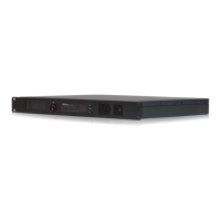
Lists the items included with the cable-access donor unit.
Lists the items included with the wireless-access donor unit.
Lists the items included with the remote unit.
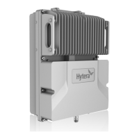
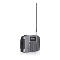
Shows the appearance of the wireless-access donor unit and the remote unit, highlighting LED indicators and connectors.
Details interfaces for cable-access and wireless-access donor units, showing numbered ports.
Details the interfaces for the remote unit, illustrating specific ports.
Provides a detailed description of each interface based on its label, connector, and function.
Defines the pin assignments and remarks for EXM and LCT interfaces.
Explains the status and description of various LED indicators on the donor and remote units.
Provides crucial safety precautions and operation instructions to avoid potential risks during installation.
Outlines the step-by-step process for installing the DS-9300 device.
Details the necessary preparations before commencing the installation process, including environment, tools, and materials.
Covers parts needed, installing units on poles/walls, and cabling requirements.
Details checks for installation integrity and device status after powering on.
Explains how to turn on the DS-9300 device using the power switch and check LED indicators.
Explains how to turn off the DS-9300 device using the power switch.
Details the preparation steps for debugging, including software and computer requirements.
Explains the process of local and remote debugging using the Product Support Software (PSS).
Describes how to manually query or auto-query parameters using the PSS software.
Details how to set parameters in the PSS software, including channel switches and frequencies.
Explains how to upgrade the monitor board and digital board programs using PSS.
Describes how to export operation logs using the PSS software.
Provides tips for product care and cleaning to ensure optimal performance and longevity.
Recommends regular check tasks to ensure reliable communication.
Lists alarm information and their corresponding solutions for troubleshooting.
Provides a table of phenomena, possible causes, and solutions for common device issues.
Lists parameters related to the device's electronic serial number, versions, IP address, and site ID.
Defines device number ranges for donor and remote units in different configurations.
Lists manufacturer IDs, with Hytera being the primary one.
Lists various device types supported by the system.
Defines the parameter for device latitude, including its subject and representation of south.
Specifies communication methods for reporting alarms, such as SNMP.
Defines the IP address for the RMS Monitor Center.
Defines the port number for the RMS Monitor Center.
Defines the site description parameter.
Section detailing parameters related to real-time sampling of device data.
Section detailing parameters for system configuration and settings.
Section detailing parameters related to alarm status and their configurations.
| Frequency Range | VHF: 136-174 MHz; UHF: 400-470 MHz |
|---|---|
| Channel Capacity | 1024 |
| Operating Voltage | 13.6 V DC |
| Modulation | 4FSK |
| Operating Temperature | -30℃ ~ +60℃ |
| Humidity | 5% to 95% |
| Cooling Method | Forced air cooling |