The Hytera HR106X Digital Repeater is a sophisticated communication device designed for enhancing radio signal coverage and reliability in various environments. This quick reference guide provides an overview of its features, installation, and basic operations.
Function Description:
The HR106X Digital Repeater serves as a central hub for extending the range and improving the quality of digital and analog radio communications. It receives signals from radio transceivers, amplifies them, and retransmits them, effectively bridging communication gaps and ensuring clear, consistent two-way radio communication across a wider area. The repeater supports both digital (DMR) and analog modes, offering flexibility for different radio systems. In advanced configurations, it can operate in a routing mode, where Ethernet interfaces 1 and 2 function as LAN and WAN ports, respectively, enabling network connectivity for enhanced communication solutions.
Important Technical Specifications:
While specific detailed technical specifications like frequency bands, power output, and sensitivity are not explicitly listed in this quick reference guide, the document highlights several key aspects:
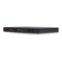
- Power Supply: The repeater can be powered by either AC (100-240V) or DC (13.6±15% V) power sources. The presence of both AC and DC power inlets on the rear panel (for both Basic and Advanced versions) indicates its adaptability to different power infrastructures.
- Connectivity:
- Antenna Connectors: Dedicated TX (Transmit) and RX (Receive) antenna connectors are provided, indicating a duplex operation where the repeater can transmit and receive simultaneously.
- Ethernet Interfaces: Both Basic and Advanced versions feature Ethernet interfaces, suggesting network integration capabilities. The Advanced version explicitly mentions two Ethernet interfaces (Ethernet Interface 1 and Ethernet Interface 2) which can serve as LAN and WAN ports in routing mode. The network interface card supports data transmission rates of 1000 Mbps/100 Mbps (glowing LED) or 10 Mbps (off LED).
- Accessory Connectors: Multiple accessory connectors (ACCY CONN1, ACCY CONN2) are available, allowing for the connection of external devices or peripherals.
- USB Connector: The Advanced version includes a USB connector, likely for programming, firmware updates, or data logging.
- Monitor/Tuning Interface: This interface is present in both versions, suggesting a dedicated port for monitoring repeater performance and fine-tuning its parameters.
- Audio/Programming Interface: The Advanced version includes an audio/programming interface, which could be used for connecting audio accessories or for programming the repeater.
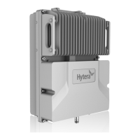
- Environmental Conditions: The repeater is designed to operate in a dry, well-ventilated place with an operating temperature range of -30°C to +60°C and relative humidity of 95%. This indicates its robustness for various indoor and potentially sheltered outdoor installations.
- Installation Site: The repeater can be installed in a rack, bracket, cabinet, or on a desk, offering versatile deployment options.
Usage Features:
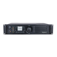
- Mode Indication: The front panel features indicators for Analog Mode and Digital Mode, allowing users to quickly identify the current operating mode.
- Timeslot Indicators: Timeslot A RX/TX and Timeslot B RX/TX indicators are present, which are crucial for DMR (Digital Mobile Radio) systems that utilize Time Division Multiple Access (TDMA) to provide two virtual channels (timeslots) on a single physical channel. These indicators show when the repeater is receiving or transmitting on a specific timeslot.
- Seven-segment Display: A seven-segment display on the front panel shows the current channel number, providing clear operational feedback.
- Volume/Channel Control: Dedicated Volume/Channel + and - keys allow users to adjust the volume and change channels. The repeater can switch between channel mode and volume mode by long-pressing the Volume/Channel + key.
- Alarm Indicator: An alarm indicator on the front panel alerts users to any operational issues or faults.
- Power Switch: Both AC and DC power switches are available for turning the repeater on or off.
- Ground Screw: A ground screw is located on the rear panel for proper grounding, which is essential for safety and performance.
Maintenance Features:
- Internal Parts Accessibility: The guide provides diagrams of the internal parts (PA Module, Main Board, Coprocessor, Power Supply Module, Wind Scooper, Fan, Control Panel, Network Board, Float Charging Board), suggesting that components may be serviceable or replaceable.
- Status Checking: The repeater provides clear status indicators for its operating mode (Digital/Analog), alarm status, timeslot activity, and power supply status.
- Digital Mode: Blue indicator when operating in digital mode.
- Analog Mode: Yellow indicator when operating in analog mode.
- Alarm: Red indicator when not working properly, with an alarm code displayed.
- Timeslot A/B RX/TX: Red for transmitting, Green for receiving (with specific behavior for Analog vs. Digital modes).
- Power Supply: Yellow for AC power, Blue for DC power, Red if unable to turn on.
- Network Interface Status: LED indicators on the Ethernet interface provide information about data transmission (flashing LED 1) and data transmission rate (glowing LED 2 for 1000/100 Mbps, off LED 2 for 10 Mbps).
- Pre-installation Tasks: The guide emphasizes preparing tools (Phillips screwdriver, T-10 torx screwdriver, spanner, anti-static gloves, multimeter) and checking the power supply voltage (13.6±15% V DC, 100-240V AC) before installation, which are good maintenance practices.
- Post-installation Check: Instructions are provided to verify proper operation after installation by observing LED indicators and the display. A yellow or blue power supply indicator and current channel display indicate proper function, while a red indicator and alarm code signal an issue.
- Safety Information: The document refers to a "Safety Information Booklet" for more details, indicating a focus on safe operation and maintenance.
- Lightning Protection: For outdoor installations in thunderstorm-prone areas, the guide recommends installing an external lightning protection module (optional) on the network interface, highlighting a key protective maintenance consideration.
- User Manual: Users are encouraged to visit the Hytera website or scan a QR code to download the User Manual for more detailed features and operations, which would include comprehensive maintenance instructions.
FCC and ISEDC Compliance:
The device complies with FCC Part 15 Class B digital device limits and ISEDC RF radiation exposure limits for occupational/controlled environments. It is designed to prevent harmful interference and must accept any interference received. Users are advised to transmit no more than 50% of the time. The antenna gain must not exceed 9.6dBi, and the antenna must be installed at least 200cm away from the human body. Any changes or modifications not expressly approved by Hytera could void the user's authority to operate the equipment.