4
LED Indicator
LED Indication Radio Status
The LED indicator
ashes green.
Powering on
The LED indicator glows
red.
Transmitting
The LED indicator glows
green.
Receiving
The LED indicator
ashes orange slowly.
Scanning or Roaming
The LED indicator
ashes orange rapidly.
Emergency
The LED indicator glows
orange.
Call hung period.
No voice is being
transmitted or received
on the traffic channel
during a call. Within
such period, you can
hold down the PTT key
to talk to the other party.
Note: Unless otherwise specified, the
PTT key mentioned in this manual
indicates that of the palm microphone.
Installation
Instructions
Before you install the radio in a vehicle, be sure to read
the following instructions carefully:
●
The radio must work with a13.6V ± 15% negative
ground electrical system only. Ensure to check the
ground polarity and voltage of the vehicle power
supply prior to installation.
●
Install the radio in a location where you can reach
the front panel conveniently.
●
Check how long the screws will extend from the
bottom surface of the radio before installation. Drill
the mounting hole cautiously to avoid damage to
the vehicle wiring and other parts.
●
Install the radio with mounting bracket supplied by
the Company, to avoid radio looseness in case of
accidents. The loose radio may cause bodily injury.
●
Connect the antenna and power cord to the radio
before you install it in the bracket. And make sure
the antenna and power cord are dedicated for
digital radios of the Company.
●
Keep sufcient clearance at the back of the radio
for wiring.
●
Be sure to use the fuse with the same specication
for DC power cord upon replacement.
●
If there are any other device in the vicinity of this
radio, the distance between the antenna of this
radio and the antenna of such RF device shall be
no less than 10 meters.
Installation Tools
●
Electric Drill
●
Cross head screwdriver
●
Hex socket sleeve (for 4.8 * 20mm self-tapping
screws)
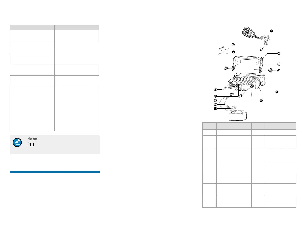
Installation Part
No. Part Name No. Part Name
1 Radio 8 Power Inlet
2 Locking Knobs 9
Power Cord
(black)
3 Mounting Bracket 10
Power Cord
(red)
4
4.8 * 20mm Self-
tapping Screws
11 Fuse
5 Palm Microphone 12
RF Antenna
Connector
6
4 * 16mm Self-
tapping Screws
13
GPS Antenna
Connector
7
Microphone
Hanger
/ /