Service Manual
CS
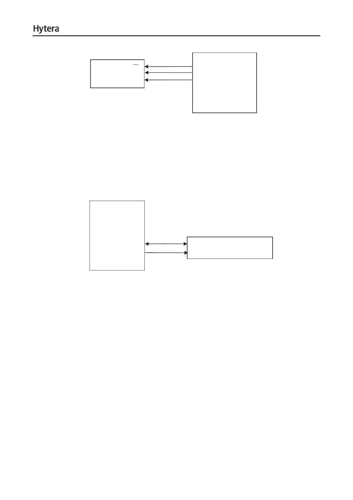
MCSI1.SYNC(W8)
MCSI1.CLK(M15)
TX/RX SKY72310 SCK
Data
MCSI1.DOUT(Y
8)
TX/RX OMAP5912
Figure 6-15 Diagram of MCSI Interfac
e
6.2.9 I
2
C
OMAP5912 provides one I
2
C interface, and supports communication rate up to 400Kbps. TX OMAP I
2
C
interface connects with PMU to dynamically adjust PMU voltage output. It works in Master mode. See
the following figure:
TX OMAP5912
U102
I2C.SDA
V20
I2C.SCL
T18
SDAT U803
SCLK
Figure 6-
16 Diagram of I
2
C Connection
6.2.10 MICROWIRE
OMAP5912 provides a MICROWIRE interface. The four chip select signals can drive four external
components. MICROWIRE interface signals include: ȝWIRE.CS, ȝWIRE.SCLK, ȝWIRE.SDO and
ȝWIRE.SDI.
In this system, only MICROWIRE interface of TX OMAP is used to connect CODEC and ADC TLV1548.
ȝWire CS0 controls CODEC and ȝWire CS3 controls ADC TLV1548. See the following figure:
17