Do you have a question about the Hyundai hirun N100 plus and is the answer not in the manual?
Explains safety alert symbols and terms like DANGER and CAUTION.
Highlights dangers associated with electrical practices and wire specifications during wiring.
Details cautions for safe electrical wiring practices for the inverter.
Outlines dangers associated with operating and monitoring the inverter.
Lists cautions for safe operation and monitoring of the inverter.
Covers dangers and cautions for troubleshooting, inspection, and maintenance procedures.
Details dangers specifically related to using the product.
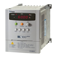
Explains the structure and meaning of inverter model numbers.
Lists general specifications applicable to all N100 inverters, covering various features.
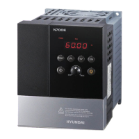
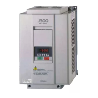
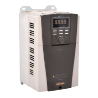
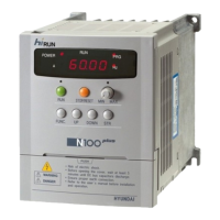
Illustrates and labels the primary physical components of the inverter unit.
Provides detailed inverter dimensions crucial for mounting and installation planning.
Details criteria for selecting an appropriate mounting location for the inverter.
Explains how to connect the main circuit wiring to the inverter.
Details the procedures for wiring the control circuit of the inverter.
Provides instructions for connecting the inverter to Programmable Logic Controllers.
Guides on selecting appropriate wiring apparatus and options for the inverter.
Details the functions of control circuit terminals for inverter operation.
Outlines crucial checks to perform before the initial power-up test.
Details the step-by-step procedure for performing the power-up test of the inverter.
Lists intelligent input terminals, their symbols, names, and functions.
Explains functions for Forward/Reverse Run/Stop commands via intelligent input terminals.
Describes selecting up to 16 different target frequencies using input terminals.
Explains how to use the Jogging Command [JG] for manual operation.
Details how to use the Second Control Function [SET] for alternate parameter sets.
Explains the Two-stage Acceleration and Deceleration feature using the [2CH] terminal.
Describes the Free-run stop function [FRS] for motor stopping.
Explains the External Trip function [EXT] for safety interlocks.
Details the Unattended Start Protection [USP] to prevent unexpected startups.
Describes the Reset Inverter function [RS] for clearing errors.
Explains the Software Lock function [SFT] to prevent parameter changes.
Describes the Frequency Arrival signals [FA1]/[FA2] for monitoring output frequency.
Explains the Run Signal [RUN] for indicating inverter operation status.
Details the Overload Advance Notice Signal [OL] for monitoring output current.
Explains the Output Deviation signal [OD] for PID control monitoring.
Describes the Alarm Signal output [AL] for fault indication.
Identifies the key parts of the inverter's control panel and display.
Provides a step-by-step procedure for operating the inverter using the standard operator.
Explains the function of each key on the inverter's operator panel.
Illustrates the navigational map for accessing expanded function modes.
Lists general precautions for keeping the inverter clean and safe during maintenance.
Details inspection items, including daily, periodic, and insulation resistance tests.
Lists essential spare parts recommended for stock to minimize downtime.
Provides tables for selecting dynamic braking resistors based on motor capacity and class.
Details the specifications and functions of the NOP 100 remote operator.
Shows external and connection diagrams for AC reactors.
Explains the function, connection, and specifications of the noise filter.
Defines the structure of communication frames for external controllers and inverter responses.
Explains the procedure for generating 16-bit CRC for communication data.