Do you have a question about the Hyundai HiRun N50 Series and is the answer not in the manual?
Highlights economy, adaptability, speed characteristics, and optional products.
Explains the structure of the model number for the HiRUN N50 series.
Details motor capacity and corresponding series types for the N50 series.
Discusses high torque at low speeds for single-phase input.
Explains current suppression for stable driving and rapid speed restoration.
Covers selection between RS485 and analog signal driving.
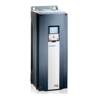
Highlights reduced volume for easier installation.
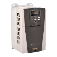
Introduces the economical remote operator for enhanced user convenience.
Visual representation of inverter dimensions for different models.
Provides detailed dimensions and weight for 007SF, 015SF, and 022SF models.
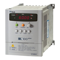
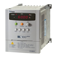
Explains the display elements and control keys on the inverter.
Step-by-step guide to configure the maximum output frequency.
Instructions for running the motor and adjusting speed using the potentiometer.
Guide on how to check the inverter's output current value.
Details motor capacity, kVA, current, and voltage for N50 models.
Covers input voltage, PWM method, control method, and frequency settings.
Specifies operating environment, storage, and IP protection level.
Details input signal options, control characteristics, and operation modes.
Explains output signals, error displays, LED indicators, and protective functions.
Lists functions for monitoring output frequency, current, voltage, and trip history.
Details settings for output frequency, acceleration, deceleration, and rotation direction.
Introduces categories for advanced functions: Basic, Fine Tuning, Terminal, Sensorless Vector.
Covers frequency commanding, base/max frequency, and external frequency start/end settings.
Details configuration for up to 15 multispeed frequency settings.
Explains settings for jog frequency and stop operation selection.
Details V/f characteristic selection, DC braking settings, and time constants.
Covers settings for frequency jump, PID gains, and feedback input.
Details acceleration/deceleration times, patterns, and input signal offset/gain.
Covers restart modes after power failure and electronic thermal level settings.
Details overload restriction levels, constant settings, and software lock functionality.
Explains settings for carrier frequency, initialization, and communication.
Details settings for intelligent input terminals and contacts (NO/NC).
Explains settings for intelligent output terminals and contacts.
Covers monitor signals, analog meter adjustments, and signal level settings.
Details auto-tuning, motor capacity, and current settings.
Covers resistance, inductance, and no-load current settings for motor constants.
Explains protection mechanisms against overcurrent, overload, and overvoltage.
Details protection against communication errors and low input voltage.
Covers protection for output short-circuits, USP, and EEPROM errors.
Describes protection triggered by external signals or internal temperature.
Details connections for main power, motor output, and grounding.
Explains signal terminals for input commands, monitoring, and frequency reference.
Details signal terminals for output status and alarm indications.
Covers wiring for fuses, contactors, and power/signal lines for different models.
Explains the function of AC reactors for harmonic suppression and vibration reduction.
Lists specs, dimensions, display, keypad, and communication for the DOP05 unit.
Explains the function of each key and LED on the digital operator interface.
Illustrates how to connect the digital operator to the inverter unit.
Guidance on operating frequency, torque, noise, and vibration for general motors.
Advice for using with gear, brake, and explosion-proof motors.
Instructions for run/stop, emergency stop, and high-frequency run operations.
Details recommended installation sites, temperature, and humidity.
Discusses input AC reactors, generator compatibility, and power supply requirements.
Covers selection of contactors, thermal relays, circuit breakers, and wiring considerations.
Addresses high-frequency noise, leakage current, and primary parts lifespan.