Do you have a question about the Hyundai J300 series and is the answer not in the manual?
Defines safety instruction symbols like WARNING and CAUTION for hazard communication.
Warns about high voltage components and necessary safety precautions during servicing.
Lists essential warnings and cautions for installation, grounding, and component protection.
Details installation requirements, including material, environment, and placement to prevent hazards.
Outlines critical wiring safety procedures, emphasizing grounding and qualified personnel.
Covers safety during operation, including cover mounting, wet hands, and terminal contact.
Stresses safety during maintenance, like waiting for discharge and using insulated tools.
Discusses installation requirements like enclosure standards and EMC filter necessity.
Advises on shielding and component placement to mitigate noise interference from the inverter.
Explains how distributor line issues can affect inverters and recommends AC reactors.
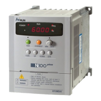
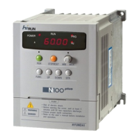
Explains how to interpret the inverter model name based on its specifications and structure.
Identifies and labels key parts of the inverter unit, including covers, terminals, and operator.
Emphasizes essential wiring safety, including grounding and using qualified electricians.
Provides diagrams for connecting power supply and motor, including notes on thermal relays and interlocks.
Shows wiring methods for control circuits, including SOURCE and SINK types with notes on diodes and shielding.
Details connection methods for programmable controllers using internal or external power sources, with sink/source types.
Lists wiring specifications for different inverter models, including power lines, signal lines, and protection devices.
Describes the layout and function of main circuit terminals for various inverter models.
Details the terminals for control circuits, including input/output signals and factory settings.
Illustrates connection diagrams for power supply, control signals, and optional components with timing notes.
Lists pre-operation checks, including safety warnings for energized components and wet hands.
Guides through the test run procedure, including pre-checks and general connection diagrams for operator or external commands.
Explains how to reset the inverter to its factory default state using terminals or power cycling.
Introduces the digital operator, its parts like display and keys, and basic operation procedures.
Demonstrates setting frequency and starting the equipment using the digital operator, step-by-step.
Explains the display contents and usage for monitor modes, such as output frequency and motor speed.
Provides procedures for returning the inverter to factory settings and deleting trip history data.
Details how to assign functions (like reverse, multi-speed, reset) to intelligent input terminals 1 through 8.
Explains how to assign functions (like frequency arrival, run signal) to output terminals 11 and 12.
Covers protection against overcurrent during operation, deceleration, acceleration, and general overload.
Details undervoltage, overvoltage, EEPROM errors, CT errors, CPU errors, and external trips.
Addresses errors detected within the power module, USP error, ground fault, and instantaneous power failure protection.
Provides a diagnostic table linking error codes (E01-E05) to causes, checks, and countermeasures.
Continues the diagnostic table with errors E06-E15, covering overvoltage, EEPROM, undervoltage, and ground faults.
Continues the diagnostic table with errors E14-E32, addressing ground faults, voltage issues, and option board errors.
Continues the diagnostic table with errors E33-E67, focusing on power module protection and J-FB PC board errors.
Outlines crucial safety steps before and during maintenance, including power disconnection and capacitor discharge.
Lists routine inspection items (daily, periodic) and specific tests like insulation resistance.
Lists instruments and parameters for measuring I/O voltage, current, power, and power factor.
Guides on connecting the digital, high-performance, or copy unit remote operators to the inverter.
Details function modes available via remote operator, including base frequency, max frequency, and start frequency settings.
Covers setting control methods (V/f, SLV) and motor constants (capacity, poles, R1, R2, L, M, J, Kp, Ti, Kpp).
Explains setting acceleration/deceleration times, curve patterns, and torque boost parameters.
Details configuration of frequency limiters, jump frequencies, and DC braking options.
Configures electronic thermal characteristics, overload restrictions, and software lock settings.
Covers overload restriction levels, constants, and free setting for electronic thermal characteristics based on current.
Configures frequency limiters, jump frequencies, running direction, and related prevention/start settings.
Details analog input configurations and settings for frequency arrival signals for acceleration/deceleration.
Explains how to assign functions to intelligent input and output terminals, including NO/NC configurations.
Configures monitor signals, trip history clearing, debug modes, and operator rotation direction.
Covers encoder settings, communication protocols (baud rate, parity), and PID control parameters.
Manages settings for option PCB errors and configures relay outputs for various signals like RUN, CST, OTQ.
Provides dimensional drawings and mounting perforation diagrams for remote operators and copy units.
Details procedures for transferring inverter data between units using the copy unit, including backup and modification.
Highlights parameters that cannot be copied by DRW/HRW units and general copying precautions.
Explains the autotuning process for automatically setting motor circuit constants for sensorless vector control.
Guides on starting autotuning via digital or remote operator and lists necessary precautions for the process.
Details the step-by-step process for performing autotuning using a new remote operator interface.
Describes the energy conservation function for V/F control to optimize voltage and suppress power, with operating precautions.
Explains the fuzzy control for optimizing acceleration/deceleration and lists precautions for its use.
Explains the function for automatic restart after instantaneous power failures, with retry modes and alarm settings.
Details how to configure commercial power source switching using digital operator function codes and remote operator input terminals.
Explains the second function setting, enabling multi-motor operation via control terminals and detailing its setup.
Lists monitor mode parameters, their display formats across different operators, and data read/copy capabilities.
Introduces PID control for regulating variables like air/water amount or pressure using feedback signals.
Guides on adjusting PID gains (P, I, D) to stabilize system response and match target values.
| Enclosure Rating | IP20 |
|---|---|
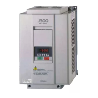
| Model | J300 Series |
| Category | Inverter |
| Output Frequency | 0-400Hz |
| Rated Output Current | Varies by model |
| Overload Capacity | 150% of rated current for 60 seconds, 200% of rated current for 3 seconds |
| Protection Functions | Overcurrent, Overvoltage, Undervoltage, Overheat, Short Circuit |
| Communication | RS485 (Modbus RTU) |
| Efficiency | >95% |
| Cooling Method | Forced air cooling |
| Operating Temperature | -10°C to +40°C |
| Storage Temperature | -20°C to +60°C |
| Ambient Humidity | 5-95% (non-condensing) |
| Altitude | Up to 1000m |