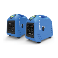
Do you have a question about the Hyundai N300-P and is the answer not in the manual?
Explains hazard alert symbols and signal words used in the manual for safety instructions.
Details warnings for electrical practices and wire specifications.
Lists tightening torque and wire range specifications for various model names.
Specifies recommended circuit breaker and fuse sizes for different inverter models.
Provides critical safety guidelines and warnings for the proper installation of the unit.
Details essential safety warnings and precautions for electrical wiring procedures.
Outlines critical safety warnings for operating the inverter and connected equipment.
Provides safety precautions for performing maintenance, inspection, and part replacement.
Covers additional safety precautions related to modifications and general handling.
Provides critical safety instructions and environmental considerations for installing the inverter unit.
Details safety warnings and precautions related to the wiring of the inverter and its components.
Illustrates the terminal connection diagram for the sink type configuration of the inverter.
Illustrates the terminal connection diagram for the source type configuration of the inverter.
Provides warnings and instructions for correctly wiring the main circuit of the inverter.
Explains how to connect power to the control circuit separately from the main power supply.
Illustrates the terminal connection diagram for control circuits, including wiring and layout.
Explains the wiring for digital operators, including remote operation via connector cables.
Details critical safety cautions for operating the inverter, including heat, speed, and test run procedures.
Explains the basic operation requirements, needing both operation and frequency settings.
Describes how to set operation and frequency via terminal control using switches, relays, or analog signals.
Introduces the explanation of inverter functions, covering monitor modes and parameter settings.
Explains different monitor modes for displaying inverter output frequency, current, direction, and PID feedback.
Explains various functional modes of the inverter, including frequency and direction settings.
Covers the selection of RUN/STOP commands and different operation command sources.
Allows setting acceleration and deceleration times, controllable via intelligent input terminals.
Covers setting the base frequency and motor voltage, crucial for motor compatibility.
Sets the V/f (voltage/frequency) characteristic for motor control.
Improves motor torque at low speeds by adjusting output voltage.
Applies DC voltage to motor windings to lock the shaft and prevent overrun.
Provides integrated process control for applications like constant flow and fan/pump control.
Manages inverter behavior during instantaneous power failures or under-voltage conditions, allowing trip or retry.
Restricts overload by reducing output frequency and provides advance notice for high loads.
Explains how to assign functions to intelligent input terminals (1-8) for flexible control.
Assigns various functions to intelligent output terminals (11-15) or the alarm relay.
Resets inverter parameters to factory defaults, including clearing trip history.
Controls external braking systems, such as those used in elevators, for precise stopping.
Selects motor constants for sensorless vector control, 0 Hz control, or vector control.
Enables serial communication with external equipment using RS485 protocol.
Details how to set the output frequency for the motor.
Protects the motor from overloading and overheating by setting parameters based on rated current.
Details various protection functions like over-current, overload, and voltage protection.
Outlines critical safety precautions and daily, cleaning, and regular inspection steps.
Details a comprehensive checklist for daily and regular inspections of inverter parts and systems.
Explains how to perform a megger test on the inverter and its terminals.
Describes a test procedure to check the quality of inverter and converter parts using a tester.
Provides detailed specifications for 200V and 400V class inverters, covering model, motor, input/output ratings, and regenerative control.
