ACON, DCON List of Specifications
Item
Description
ACON-CA/CB/CGB DCON-CA/CB/CGB
Number of controlled axes 1-axis
Power-supply Voltage
24V DC 10%
Load
Capacity
(It does not
including
control side
current
consumption)
(Note1)
Series Motor Type
Rated
Max. Power
Consumption
MAX.
(Note5)
Rated MAX.
RCA,
RCA2,
RCL
2W 0.8A 4.6A
5W 1.0A 6.4A
10W
RCL
1.3A 6.4A
10W (RCA/ RCA2) 1.3A 2.5A 4.4A
20W 1.3A 2.5A 4.4A
20W
Model: 20S
1.7A 3.4A 5.1A
30W 1.3A 2.2A 4.0A
RCD 3W 0.7A 1.5A
Power Supply for Electromagnetic Brake
for actuator equipped with brake
24V DC 10% 0.15A (MAX.)
Heat Generation 8.4W 4W
Rush Curren
(Note2)
10A
Transient Power Cutoff Durability
MAX. 500s
Motor Control S
stem Sinusoidal Waveform
AC
Drive Rectan
ular Waveform
DC
Drive
Corresponding Encoder Incremental Encoder
Serial Absolute Encoder
Batter
-less Aboslute Encode
Incremental Encoder
Corresponding
Encoder
Resolution
RCA Incremental Type 800pulse/rev
Serial Absolute T
pe 16384pulse/rev
RCA2 RCA2_*** N 1048pulse/rev
Other than
RCA2_*** N
800pulse/rev
RCA
/RCA2
Batte
y-less
Absolute Type
16384pulse/rev
RCL RA1, RA4, SA1, SA4 715pulse/rev
RA2, RA5, SA2, SA5 855pulse/rev
RA3, RA6, SA3, SA6 1145pulse/rev
RCD
400pulse/rev
Actuator Cable Len
th MAX. 20m MAX. 10m
Serial Communication Interface
SIO Port
RS485 : 1 CH (based on Modbus Protocol RTU/ASCII) Speed : 9.6 to 230.4Kbps
Control available with serial communication in the modes other than the pulse train
External Interface PIO Type Signal I/O dedicated for 24V DC (selected from NPN/PNP) … Input 16 points max.,
output 16 points max. Cable len
th MAX. 10m
Fieldbus Type
DeviceNet, CC-Link, PROFIBUS-DP, CompoNet, MECHATROLINK-Ⅰ/Ⅱ,
EtherCAT, EtherNet/IP, PROFINET-IO, MECHATROLINK-Ⅲ (Except for ACON-CA
and DCON-CA
Data Settin
and Inpu
PC Software, Touch Panel Teachin
, Teachin
Pendant, Data Sette
Data Retention Memory Saves position data and parameters to non-volatile memory
There is no limitation to the number of times data ma
be written.
Operation Mode Positioner Mode/Pulse Train Control Mode
selected b
parameter settin
Number of Positions in Positioner Mode Standard 64 points, MAX. 512 points (PIO Type)
Note
Number of positions differs dependin
on the selection in PIO pattern.
Pulse Train
Interface
(Note4)
Input Pulse Frequency Differential System (Line Driver System) : MAX. 200kpps
Cable len
th MAX. 10m
Open Collector System : Not applicable.
* If the host applies the open collector output, prepare AK-04 (option) separately to
convert to the differential t
pe.
Command Pulse Multiplying
Factor (Electrical Gear : A/B)
1/50 A/B 50/1
Settin
Ran
e of A and B
set to parameter
: 1 to 4096
Feedback Pulse Output None
LED Display
(mounted on Front Panel)
SV (GN)/ALM (RD) : Servo ON/Alarm generated
STS0 to 3 : Status display
RDY (GN)/ALM (RD) : Absolute function in normal / absolute function error (for the simple
absolute type)
1, 0
GN
RD
: Absolute function status displa
for the simple absolute t
pe
Electromagnetic Brake Compulsory
Release Switch
mounted on Front Panel
Switching NOM (standard)/BK RLS (compulsory release)
Insulation Resistance
500V DC 10M or more
Protection Function a
ainst Electric Shoc
Class I basic insulation
Weight
(Note3)
(Other than
Field
Network
Type)
Incremental Type Screw fixed type : 230g or less
DIN rail fixed t
pe : 265
or less
Simple Absolute Type Battery (AB-7) : 190g or less
Absolute Battery Case (SEP-ABU):
140
or less
Serial Absolute T
pe Batter
AB-5
: 20
Coolin
Method Natural ai
-coolin
External dimensions Screw fixed t
pe : 35W×178.5H×69.6D DIN rail fixed t
pe : 35W×185H×78.1D
Environment
Surrounding Air Temperature
0 to 40C
Surroundin
Humidit
5%RH to 85%RH or less
There should be no condensation or freeze
Surroundin
Environmen
[Refer to Installation Environment]
Surrounding Storage
Temperature
-20 to 70C (Excluding battery)
Usa
e Altitude 1000m or less
Protection Class IP20
Vibration Durability Frequency 10 to 57Hz / Swing width : 0.075mm
Frequency 57 to 150Hz / Acceleration 9.8m/s
2
XYZ directions Sweep time : 10 minutes Number of sweep : 10 times
Note1 Control power capacity is 0.3A.
Note2 In-rush current will flow for approximately 5ms after the power is turned on (at 40C).
Note that the value of in-rush current differs depending on the impedance of the power supply line.
Note3 Add the weight of the battery (case) for “Simple Absolute Type” and “Serial Absolute Type”.
Note4 Serial absolute type is not applicable for the pulse train control mode.
Note5 The current reaches the maximum at the excitation phase detection of the motor conducted when the servo is turned on
for the first time after the power is supplied. (TYP 1 to 2 second, MAX. 10 second)
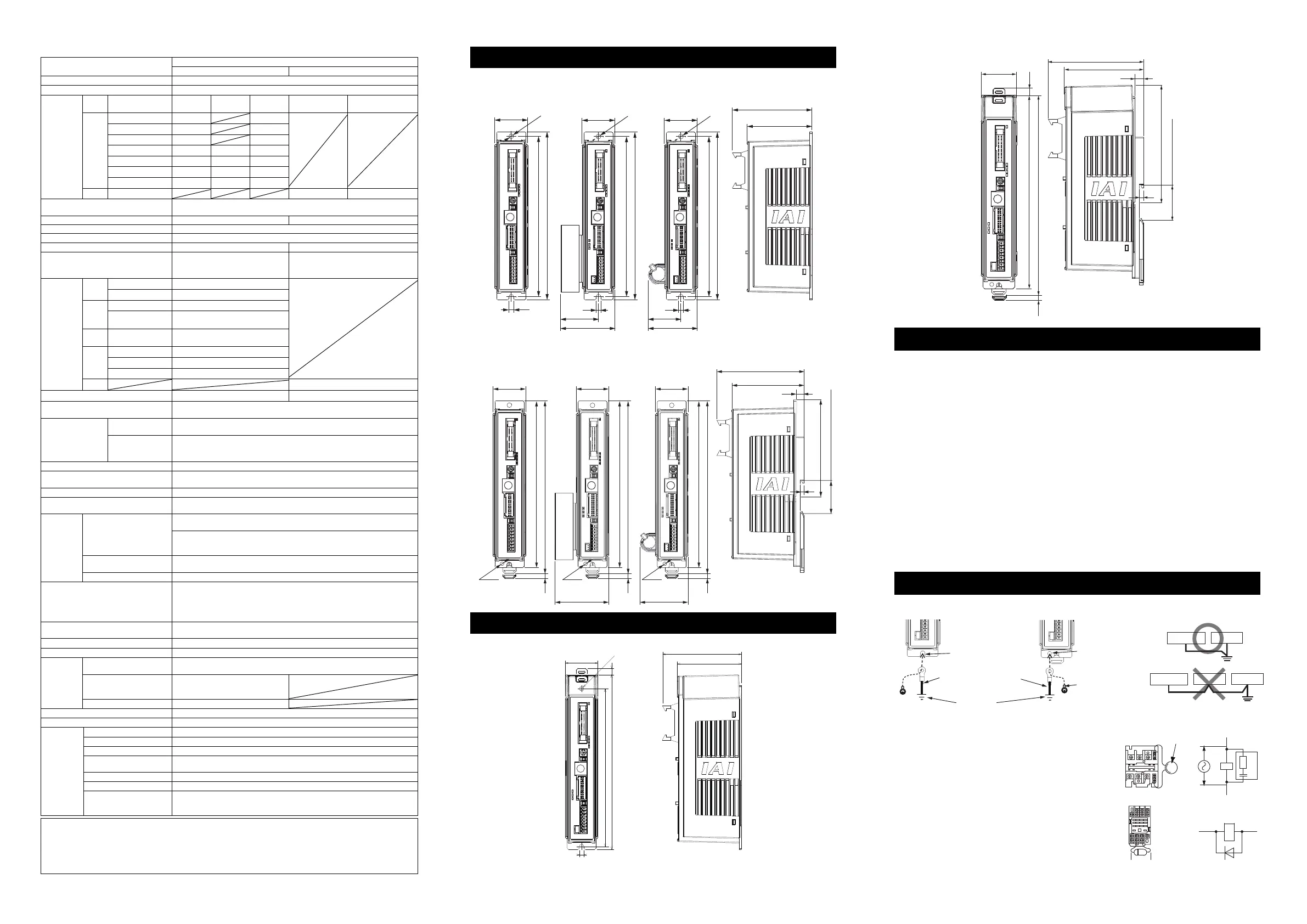
External Dimensions (ACON, DCON and PCON-CA/CB/CGB/CBP/CGBP)
● Screw fixed type
Battery-less Absolute/ Simplified Absolute Type Serial Absolute Type Side View
Incremental Type (Option) (Option)
84.8
69.6
35
φ
5
170.5
178.5
5
35
φ
5
5
(40.5)
(58)
170.5
178.5
35
φ
5
5
(34.5)
(52)
170.5
178.5
● DIN rail fixed type
Battery-less Absolute/ Simplified Absolute Type Serial Absolute Type Side View
Incremental Type (Option) (Option)
35
178.5
185
(5)
M3
(for FG cable
attachment)
93.6
78.1
8.5
4
104 from DIN rail center
35.4 (Width of 35mm DIN rail)
M3
35
178.5
185
(5)
(52)
(for FG cable
attachment)
M3
35
178.5
185
(5)
(58)
(for FG cable
attachment)
External Dimensions (PCON-CFA/CFB/CGFB)
● Screw fixed type
35
φ
5
5
84.8
69.6
190
170.5
(7)
(Note) When using the
attachment hole
on the top of the
controller, detach
the fan unit
temporarily.
● DIN rail fixed type
(7)
35
93.3
78.1
8.5
4
115 from DIN rail center
35.4 (Width of 35mm DIN rail)
190
(5)
196.5
Installation Environment
This product is capable for use in the environment of pollution degree 2
*1
or equivalent.
*1 Pollution Degree 2: Environment that may cause non-conductive pollution or transient conductive
pollution by frost (IEC60664-1)
1. Installation Environment
Do not use this product in the following environment
Location where the surrounding air temperature exceeds the range of 0 to 40C
Location where condensation occurs due to abrupt temperature changes
Location where relative humidity exceeds 5%RH to 85%RH
Location exposed to corrosive gases or combustible gases
Location exposed to significant amount of dust, salt or iron powder
Location subject to direct vibration or impact
Location exposed to direct sunlight
Location where the product may come in contact with water, oil or chemical droplets
Environment that blocks the air vent [Refer to Installation and Noise Elimination]
A place with its altitude more than 1000m
When using the product in any of the locations specified below, provide a sufficient shield.
Location subject to electrostatic noise
Location where high electrical or magnetic field is present
Location with the mains or power lines passing nearby
2. Storage and Preservation Environment
Storage and preservation environment follows the installation environment. Especially in a long-term storage, consider
to avoid condensation of surrounding air.
Unless specially specified, moisture absorbency protection is not included in the package when the machine is
delivered. In the case that the machine is to be preserved in an environment where dew condensation is anticipated,
take the condensation preventive measures from outside of the entire package, or directly after opening the package.
Installation and Noise Elimination
1. Noise Elimination Grounding (Frame Ground)
2. Precautions regarding wiring method
1) Wire is to be twisted for the 24V DC power supply.
2) Separate the signal and encoder lines from the power
supply and power lines.
3. Noise Sources and Elimination
Carry out noise elimination measures for power devices on
the same power path and in the same equipment.
The following are examples of measures to eliminate noise
sources.
1) AC solenoid valves, magnet switches and relays
[Measure] Install a Surge absorber parallel with the coil.
2) DC solenoid valves, magnet switches and relays
[Measure] Install a diode parallel with the coil. Use a DC
relay with a built-in diode.
Surge absorber
Relay
coil
Relay coil
R
C
+24V 0V
+24V 0V
+-
Do not share the ground wire with or connect
to other equipment. Ground each controller.
Controller
Other
equipment
Controller
Other
equipment
Other
equipment
Connect the ground cable
using the tapped hole for
FG connection on the main unit.
M3 × 5 nickeled pan head
machine screw
(enclosure dedicated for
DIN rail fixed type)
Screw fixed type DIN rail fixed type
Connect the ground line
together to the main unit
using the fixing screw.
Copper wire:
Connect a ground wire with a
diameter of 1.6mm (2mm
2
) or larger.
Earth Terminal
Grounding resistance 100Ω or less
(Class D grounding)

 Loading...


