Signal Assignments in Each Mode
The signal assignment of I/O flat cable by the PIO pattern is as shown below. Follow the following table to connect the external
equipment (such as PLC).
Pin
No.
Category
PIO Functions
Selection in Parameter No. 25
PIO Pattern
0 1 2 3 4 5
6
(Note1)
7
(Note1)
Positioning
mode
Teaching
mode
256-point
mode
512-point
mode
Electro-
magnetic
valve mode
1
Electro-
magnetic
valve mode
2
Force
Sensor Used
Pressing
Mode 1
Force Sensor
Used
Pressing
Mode 2
Input
Number of
Positionin
Points
64 points 64 points 256 points 512 points 7 points 3 points 32 points 5 points
Home Return
Si
nal
Jog Signal
Teaching Signal
(Current Position
Writing)
Brake Release
Output
Signal during
Operation
Zone Signal
(Note2)
(Note2)
Position Zone
Si
nal
1A 24V P24
2A 24V P24
3
4
5A
Input
IN0 PC1 PC1 PC1 PC1 ST0 ST0 PC1 ST0
6A IN1 PC2 PC2 PC2 PC2 ST1
ST1
(JOG)
PC2 ST1
7A IN2 PC4 PC4 PC4 PC4 ST2
ST2
(Note2)
PC4 ST2
8
IN3 PC8 PC8 PC8 PC8 ST3
PC8 ST3
9
IN4 PC16 PC16 PC16 PC16 ST4
PC16 ST4
10A IN5 PC32 PC32 PC32 PC32 ST5 – – –
11A IN6 – MODE PC64 PC64 ST6 – – –
12
IN7
JISL PC128 P128
13A IN8 –
JOG
– PC256 – – CLBR CLBR
14A IN9 BKRL
JOG
BKRL BKRL BKRL BKRL BKRL BKRL
15
IN10 RMOD RMOD RMOD RMOD RMOD RMOD RMOD RMOD
16
IN11 HOME HOME HOME HOME HOME
HOME HOME
17A IN12 *STP *STP *STP *STP *STP – *STP *STP
18A IN13 CSTR
CSTR/PW
RT
CSTR CSTR – – CSTR –
19A IN14 RES RES RES RES RES RES RES RES
20
IN15 SON SON SON SON SON SON SON SON
1B
Output
OUT0
PM1
(ALM1)
PM1
(ALM1)
PM1
(ALM1)
PM1
(ALM1)
PE0 LS0
PM1
(ALM1)
PE0
2B OUT1
PM2
(ALM2)
PM2
(ALM2)
PM2
(ALM2)
PM2
(ALM2)
PE1
LS1
(TRQS)
PM2
(ALM2)
PE1
3B OUT2
PM4
(ALM4)
PM4
(ALM4)
PM4
(ALM4)
PM4
(ALM4)
PE2
LS2
(Note3)
PM4
(ALM4)
PE2
4B OUT3
PM8
ALM8
PM8
ALM8
PM8
ALM8
PM8
ALM8
PE3 –
PM8
ALM8
PE3
5B OUT4 PM16 PM16 PM16 PM16 PE4 – PM16 PE4
6B OUT5 PM32 PM32 PM32 PM32 PE5 – TRQS TRQS
7B OUT6 MOVE MOVE PM64 PM64 PE6
LOAD LOAD
8B OUT7 ZONE1 MODES PM128 PM128 ZONE1 ZONE1 CEND CEND
9B OUT8
PZONE/
ZONE2
PZONE/
ZONE1
PZONE/
ZONE1
PM256
PZONE/
ZONE2
PZONE/
ZONE2
PZONE/
ZONE2
PZONE/
ZONE2
10B OUT9 RMDS RMDS RMDS RMDS RMDS RMDS RMDS RMDS
11B OUT10 HEND HEND HEND HEND HEND HEND HEND HEND
12B OUT11 PEND
PEND/
WEND
PEND PEND PEND – PEND PEND
13B OUT12 SV SV SV SV SV SV SV SV
14B OUT13 *EMGS *EMGS *EMGS *EMGS *EMGS *EMGS *EMGS *EMGS
15B OUT14 *ALM *ALM *ALM *ALM *ALM *ALM *ALM *ALM
16B
OUT15
(Note3)
LOAD/TRQS
*ALML
/*BALM
*ALML
/*BALM
LOAD/TRQS
*ALML
/*BALM
LOAD/TRQS
*ALML
/*BALM
LOAD/TRQS
*ALML
/*BALM
*BALM/
*ALML
*ALML *ALML
17B
18B
19B 0V N
20B 0V N
(Note) “*” in codes above shows the signal of the active low.
PM1 to PM8 indicate the alarm binary code output signal when an alarm is generated. [Refer to the Instruction Manual
for the details]
(Note 1) PIO Patterns 6 and 7 should be available only when PCON-CBP/CGBP are ordered at purchasing.
(Note 2) The setting can be changed over to PZONE if set in the parameter setting.
(Note 3) It is invalid before home-return operation.
(Note 4) *BALM is dedicated for ACON.
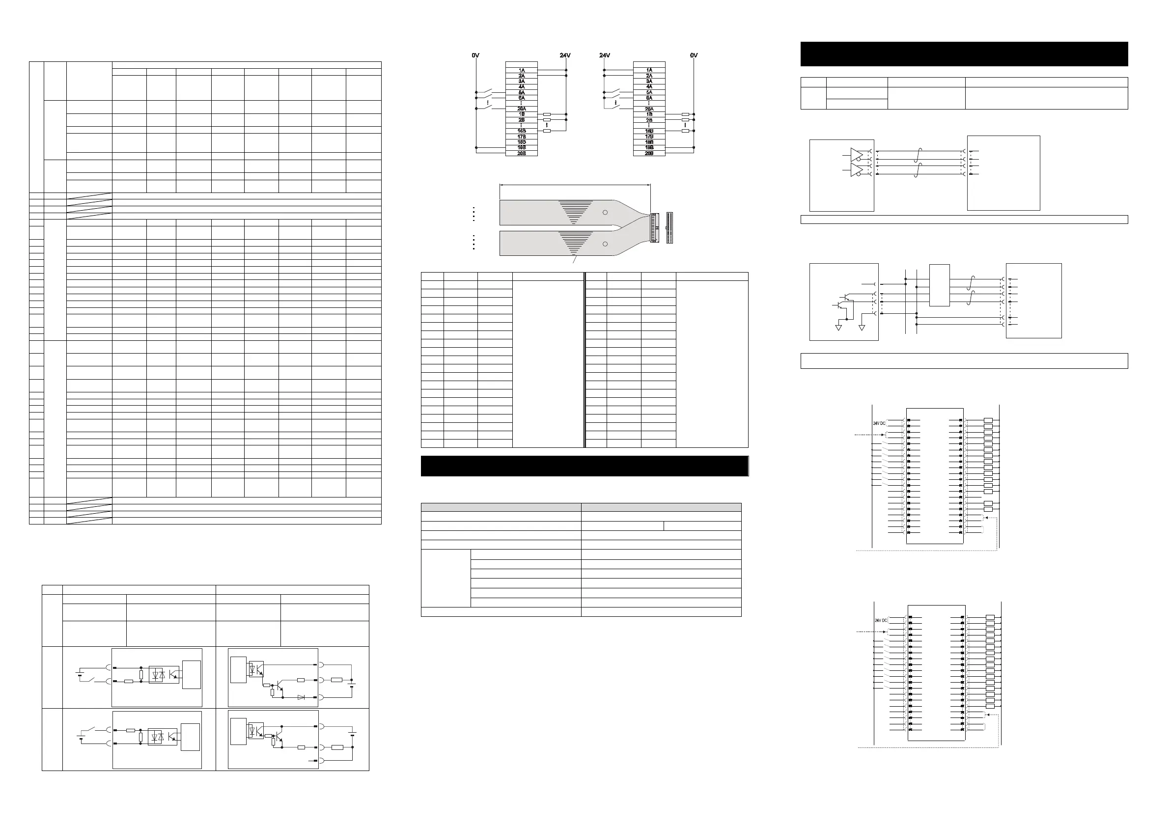
PIO Input and Output Interface
Input section Output section
Specification
Input voltage 24V DC10% Load voltage 24V DC
Input current 5mA 1 circuit
Peak load electric
current
50mA/1 point
ON/OFF voltage
ON voltage MIN. 18V DC
OFF voltage MAX. 6V DC
Leak Current
MAX. 2mA/1 point (PCON)
MAX. 1mA/1 point
(ACON, DCON)
NPN
680
5.6K
P24
External
Power Supply
24V DC
Input
Terminal
Internal
Power
Source
Controller
15
P24
N
Load
External
Power Supply
24V DC
Output
Terminal
Internal
Power
Source
Controller
PNP
680
5.6K
N
External
Power Supply
24V DC
Input
Terminal
Internal
Power
Source
Controller
15
P24
N
Load
External
Power Supply
24V DC
Output
Terminal
Internal
Power
Source
Controller
NPN Specification PNP Specification
I/O Cable
Model : CB-PAC-PIO□□□
(Enter the cable length (L) in □□□ Example. 020 2m)
No. Signal Name Cable Color Wiring No. Signal Name Cable Color Wiring
1A 24V BR-1
Flat Cable
○
A
(Insulation-Displacement
Connectors)
AWG28
1B OUT0 BR-3
Flat Cable
○
B
(Insulation-Displacement
Connectors)
AWG28
2A 24V RD-1 2B OUT1 RD-3
3A PP OR-1 3B OUT2 OR-3
4A /PP YW-1 4B OUT3 YW-3
5A IN0 GN-1 5B OUT4 GN-3
6A IN1 BL-1 6B OUT5 BL-3
7A IN2 PL-1 7B OUT6 PL-3
8A IN3 GY-1 8B OUT7 GY-3
9A IN4 WT-1 9B OUT8 WT-3
10A IN5 BK-1 10B OUT9 BK-3
11A IN6 BR-2 11B OUT10 BR-4
12A IN7 RD-2 12B OUT11 RD-4
13A IN8 OR-2 13B OUT12 OR-4
14A IN9 YW-2 14B OUT13 YW-4
15A IN10 GN-2 15B OUT14 GN-4
16A IN11 BL-2 16B OUT15 BL-4
17A IN12 PL-2 17B NP PL-4
18A IN13 GY-2 18B /NP GY-4
19A IN14 WT-2 19B 0V WT-4
20A IN15 BK-2 20B 0V BK-4
Loadcell (PCON-CBP/CGBP Dedicated Option)
It is a pressing force measurement unit used in the force control.
It should be used by connecting to an actuator applicable for the force control or servo pressing.
[Specification]
Item S
ecification
Loadcell System Strain Gauge
Rated Capacity [N] 600 2000
Total Accuracy [% F.S.] ±1
Allowable Overload [% F.S.] 200
Environmental
Specifications
Surrounding Air Temperature
0 to 40 C
Surrounding Humidity
85%RH o
less (non-condensing)
Surrounding Environment
Should be no corrosive gas
Surrounding Storage Temperature
-10 to 60 C
Ambient Humidity for Storage
90%RH less (non-condensing)
Vibration Resistance
10 to 57Hz in X, Y and Z di
ections
Dielectric Withstanding Voltage [V] DC50V
* F.S.(Withstand Load)
Note The number of actuators available to connect should differ depending on the rated capacity of a loadcell.
[Check in an instruction manual of an actuator for how to install and details of dimensions.]
Operation in Pulse Train Control Mode
function for PLN and PLP T
pes onl
Pulse Train Input and Output Interface
Categor
Abbreviated Code Signal Name Contents of Functions
Input
PP, /PP
Command Pulse Input
Inputs the command pulse train.
Input pulse frequency differs depending on the type.
[Refer to Basic Specifications]
NP, /NP
● When Host Unit is Differential System
(Although the example shows PCON, it is the same for ACON and DCON.)
Note1 : Use the same power source (0V) for the host open collector output, AK-04.
● When Host Unit is Open Collector System [AK-04 (option) is required]
(Although the example shows PCON, it is the same for ACON and DCON.)
Note1 : 1) Use the same power source (0V) for the host open collector output, AK-04.
2) Have the cables as short as possible between the host unit and AK-04.
PIO Pattern 6 ... Pulse Train Control Mode (for incremental type actuators)
PIO Pattern 7 ... Pulse Train Control Mode (for Absolute type actuators)
* shows a signal in active low. The input signal should be processed when it turns off, and the output signal should ordinary be
on while the power is turned on and turns off when the signal gets output.
Pin No.
Pin No.
Load
Load
Flat Cable (20-core)
×
2
BK-4
BR-3
BK-2
BR-1
No treatment
conducted
No treatment
conducted
20A 20B
1A 1B
Half Pitch MIL Socket
HIF6-40D-1.27R (Hirose Electric)
A
B
L
0V
24V
DC
0V
0V
1
2
3
4
1
2
3
4
PCON
PIO Connector
3A
4A
17B
18B
19B
20B
Host Unit
Positioning Unit
Pulse
Command
0V
0V
PP
/PP
NP
/NP
/PP
PP
NP
/NP
NP
PP
0V
24V
Pulse Converter
AK-04
(to be purchased separately)
24V
PCON
PIO Connector
3A
4A
17B
18B
Host Unit
Positioning Unit
Pulse Command
(Line Driver:
26C31 or equiv.)
PP
/PP
NP
/NP
0V
NPN T
pe
BR- 1
1A
P24
PWR
1B
BR- 3
0V
24V DC(NPN Type)
24V DC(PNP Type)
RD- 1
2A
P24 SV
2B
RD- 3
0V(PNP Type)
OR- 1
3A
SON
INP
3B
OR- 3
System Ready
YW- 1
4A
RES
HEND
4B
YW- 3
Servo ON Status
GN- 1
5A
HOME
TLR
5B
GN- 3
BL- 1
6A
TL
6B
BL- 3
PL- 1
7A
CSTP
7B
PL- 3
Deviation Counter Clear
GY- 1
8A
DCLR
8B
GY- 3
Brake Control Release
Compulsory Stop
Torque Limit Select
WT- 1
9A
BKRL
ZONE1
ZONE2
9B
WT- 3
Operation Mode
BK- 1
10A
RMOD
RMDS
10B
BK- 3
Zone 2
Zone 1
Home Return
BR- 2
11A
ALM1
ALM2
ALM4
ALM8
11B
BR- 4
RD- 2
12A
12B
RD- 4
Operating Mode Status
Emergency Stop Status
OR- 2
13A
13B
OR- 4
Home Return Completion
Torque Under Control
Reset
YW- 2
14A
*EMGS
14B
YW- 4
Position Completion
Servo ON
GN- 2
15A
*ALM
15B
GN- 4
BL- 2
16A 16B
BL- 4
PL- 2
17A
N
17B
PL- 4
Alarm Code Output 1
Alarm
Alarm Code Output 2
Alarm Code Output 4
Alarm Code Output 8
GY- 2
18A
N
18B
GY- 4
WT- 2
19A
19B
WT- 4
BK- 2
20A
20B
BK- 4
PCON
PIO Connector
NC/*ALML
None/Light Error Alarm Output
PP
/PP
NP
/NP
Differential Pulse Supply
[Refer to the next page for
the details of wiring.]
Differential Pulse Supply
[Refer to the next page for
the details of wiring.]
0V
NPN T
pe
BR- 1
1A
P24
PWR
1B
BR- 3
0V
24V DC(NPN Type)
24V DC(PNP Type)
RD- 1
2A
P24 SV
2B
RD- 3
0V(PNP Type)
OR- 1
3A
SON
INP
3B
OR- 3
System Ready
YW- 1
4A
RES
HEND
4B
YW- 3
Servo ON Status
GN- 1
5A
HOME
TLR
5B
GN- 3
BL- 1
6A
TL
6B
BL- 3
PL- 1
7A
CSTP
7B
PL- 3
Deviation Counter Clear
GY- 1
8A
DCLR
8B
GY- 3
Brake Control Release
Compulsory Stop
Torque Limit Select
WT- 1
9A
BKRL
ZONE1
REND
ZONE2
9B
WT- 3
Operation Mode
Datum Position Movement Command
BK- 1
10A
RMOD
RSTR
RMDS
10B
BK- 3
Zone 2
Zone 1
Home Return
BR- 2
11A
ALM1
ALM2
ALM4
ALM8
11B
BR- 4
RD- 2
12A
12B
RD- 4
Operating Mode Status
Emergency Stop Status
OR- 2
13A
13B
OR- 4
Home Return Completion
Torque Under Control
Reset
YW- 2
14A
*EMGS
14B
YW- 4
Position Completion
Servo ON
GN- 2
15A
*ALM
15B
GN- 4
BL- 2
16A 16B
BL- 4
PL- 2
17A
N
17B
PL- 4
Alarm Code Output 1
Alarm
Alarm Code Output 2
Alarm Code Output 4
Alarm Code Output 8
GY- 2
18A
N
18B
GY- 4
WT- 2
19A
19B
WT- 4
BK- 2
20A
20B
BK- 4
ACON, DCON
PIO Connector
NC/*ALML
None/Light Error Alarm Output
Datum Position Movement Complete
PP
/PP
NP
/NP
Differential Pulse Supply
[Refer to the next page for
the details of wiring.]
Differential Pulse Supply
[Refer to the next page for
the details of wiring.]

 Loading...


