2.2 Motor Reversing Type
The direction of the motor is either left reversed: ML (shown in figure above) or right reversed: MR.
For the details of dimensions and outlines, refer to the catalog or Instruction Manual (DVD).
Attachment
Refer to the Instruction Manual (DVD) for the attachments of the actuator and loads.
[Precautions for Attachments]
No. Item Precautions
1 Installation
• Installing the slider type in the horizontally oriented wall mount or ceiling mount may
cause the stainless steel sheet to be loosened or be off the right position.
Continued use of the actuator with this condition may result in the breakage of the
stainless steel sheet. Adjust the sheet tension accordingly in the regular inspection.
(Refer to the maintenance section on the Instruction Manual for the procedure of
stainless steel sheet tension adjustment.)
• Avoid using the actuator with no brake in the vertical orientation.
2 Attachment Surface
• The base has to have a structure with sufficient rigidity to prevent oscillation.
• The side and the bottom surfaces of the base of the actuator are the datum for the
slider drive. If accuracy for its run is required, use these surfaces as a datum of the
installation.
Reference Surface
(Side of Base)
Reference Surface
Reference Surface
Reference Surface
(Side of Base)
• The actuator mounting surface and other surfaces that are used as a datum should
be flat enough with an accuracy of machining or equivalent treatment, and the
flatness of the mounting surface needs to be 0.05mm/m or less.
• Secure the space where maintenance work can be performed.
3 Bolt to be used
• For the bolts to be used, a high-tensile bolt complying with ISO-10.9 or more is
recommended.
• If using the tapped holes, use screws with the thread length dimension being less
than the effective depth of the holes.
• In case the tapped hole is a through hole, be careful so the screw tip does not
exceed the surface of the tapped hole.
• For the actuator mounting, use a bolt with the dimension of its effective mating
length to the tapped hole is as stated below.
If tapped hole on steel → thread length same as nominal diameter
If tapped hole on aluminum → thread length 1.8 times longer than nominal diameter
4 Tightening Torque
• Please follow the specification values stated in the Instruction Manual (DVD) for the
tightening torque.
Failure to do so may cause an operation problem.
5 Load Moment and
Overhung length
• Please follow the specification values stated in the Instruction Manual (DVD) for the
load moment and the overhung length. Failure to do so may cause abnormal
vibration or noise, and also may remarkably shorten the product life.
6 Stainless sheet
• Please do not hold the stainless steel sheet directly with hands. Please, also, be
careful not to make a dent on the stainless steel sheet.
Stainless sheet is easy to get dented because it is thin. Using it with a dent on may
cause a breakage.
• If there is dust or metal contamination attached on the stainless steel sheet, please
wipe it off the sheet surface. Operation with the stainless sheet that has foreign
matters on its surface may cause problems such as sheet damage, waviness, etc.
inside the slider.
• Please do not operate the unit in the ambient with dust or metal contamination.
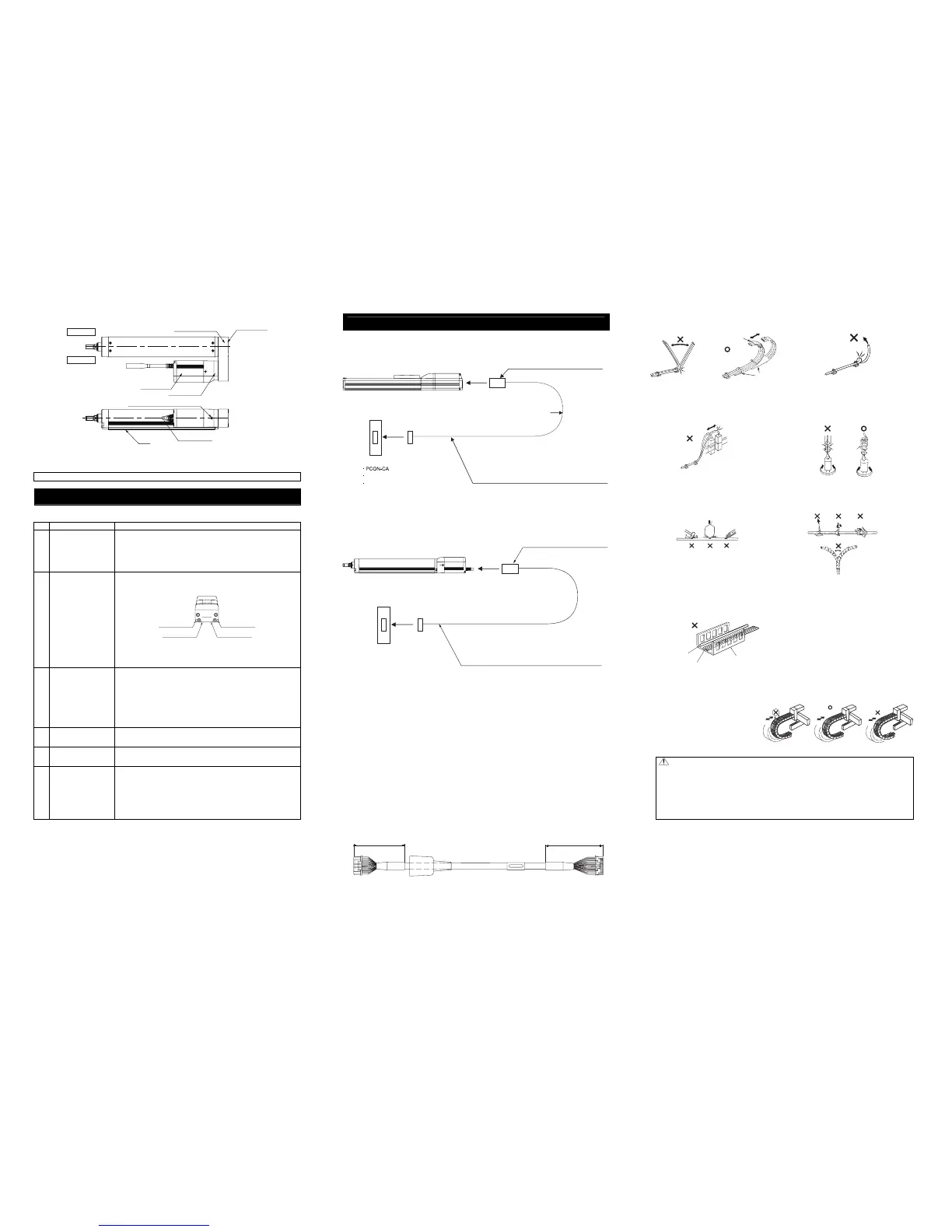
Wiring
For the controller, only the dedicated controller manufactured by our company can be used.
For the connection between the actuator and controller, use the attached dedicated connection cable.
[Connection to the controller]
RCP4-SA3, RA3
Dedicated connection cable
(Connect RCP4 with the dedicated controller)
Dedicated connection cable
• Motor • encoder integrated cables: CB-CAN-MPA□□□
• Motor • encoder integrated cables robot type: CB-CAN-MPA□□□-RB
r
Robot Cable
: 5m or less
: 5m then longer cases
Standard cable
: 5m or less
: 5m then longer cases
Dedicated controller
*) □□□ indicates the cable length. Up to 20m can be specified.
Example) 080 = 8m
MSEP
MSEL
r=68mm or more (Movable Use)
r=73mm or more (Movable Use)
r=85mm or more (Fixed Use)
r=91mm or more (Fixed Use)
Note 1 Only the motor type of rod type 56SP is applicable for PCON-CFA Controller.
[Prohibited Items in the Cable Processing]
• Do not pull or bend forcibly the cable so as not to give any extra load or tension to the
cable.
• Do not process the cable for extension or shortening by means of cutting out,
combination or connecting with another cable.
• Do not bend the cable in the area from the connector tip to 150mm on the both ends.
Standard cable : CB-CA-MPA□□□, CB-CFA2-MPA□□□, CB-CAN-MPA□□□
Robot cable : CB-CA-MPA□□□-RB, CB-CFA2-MPA□□□-RB, CB-CAN-MPA□□□-RB
150mm 150mm
• Do not let the cable flex at a single
point.
• Do not let the cable bend, kink or twist.
• Do not pull the cable with a strong
force.
• Do not let the cable receive a turning force
at a single point.
• Do not pinch, drop a heavy object
onto or cut the cable.
• When fixing the cable, provide a moderate
slack and do not tension it too tight.
• Separate the I/O line, communication
line and power line from each other.
Do not store in the same duct.
Follow the instructions below when using a
cable track.
• If there is an indication to the cable for the
space factor in a cable track, refer to the
wiring instruction given by the supplier
when storing the cable in the cable track.
• Avoid the cables to get twined or twisted in
the cable track, and also to have the
cables move freely and do not tie them up.
(Avoid tension being applied when the
cables are bent.)
Do not pile up cables. It may cause faster
abrasion of the sheaths or cable
breakage..
Note:
• When the cable is connected or disconnected, make sure to turn off the power to the
controller. When the cable is connected or disconnected with the controller power turned
ON, it might cause a malfunction of the actuator and result in a serious injury or damage
to the machinery.
• When the connector connection is not correct, it would be dangerous because of a
malfunction of the actuator. Make sure to confirm that the connector is connected
correctly.
Steel Strap
(Piano Wire)
Tie them up softly.
Do not use spiral tube in any
position where cables are bent
frequently.
Power Line
Duct
I/O Line
(Flat Cable, etc.)
Actuator Cable
Base
Motor Unit
Screw for Motor Unit Attachment
Pulley Cover
Right Side
Left Side
Reversing Bracket
Pulley Bracket
Other than RCP4-SA3 and RA3
Dedicated connection cable
(connects controller and RCP4)
Dedicated controller
• PCON-CA
• PCON-CFA
(Note 1)
: 5m then longer cases
: 5m or less
r=80mm or more (Movable Use)
r=68mm or more (Movable Use)
: 5m then longer cases
: 5m or less
Standard Cable
Robot Cable
r=85mm or more (Fixed Use)
r=91mm or more (Fixed Use)
Dedicated connection cable
Motor-encoder : CB-CA-MPA□□□
Motor-encoder robot cable : CB-CA-MPA□□□-RB
(Note) □□□ indicates the cable length. Up to 20m can be specified.
Example) 080=8m
[For PCON-CA, MSEP/MSEL]
Motor-encoder : CB-CFA2-MPA□□□
Motor-encoder robot cable : CB-CFA2-MPA□□□-RB
[For PCON-CFA]
• MSEP
• MSEL

 Loading...


