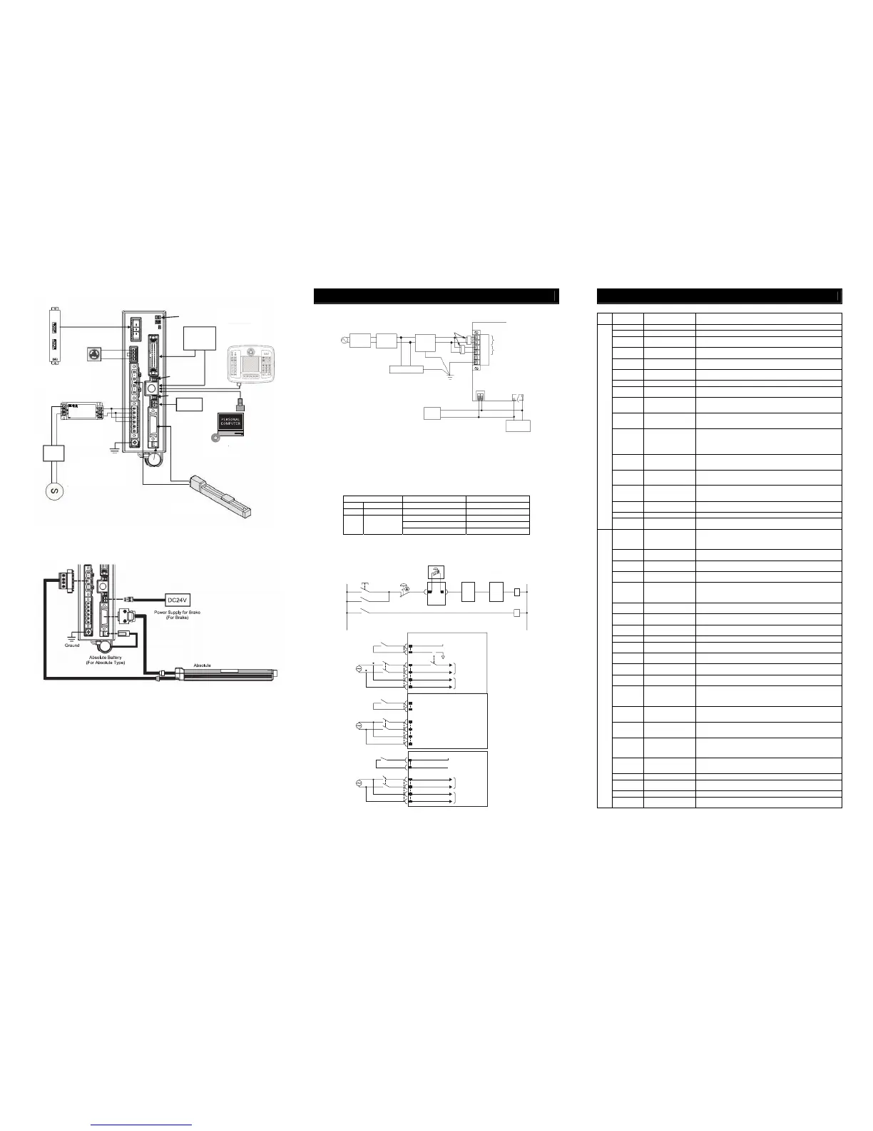
SCON-CAL/CGAL
EMG Switch
Regenerative Resistor Unit
Required in some conditions of use.
Noise Filter
Required for noise
prevention.
Host
Control
System
Circuit Breaker
Select a circuit breaker
applicable for the capacity
of the controller.
Actuator
PC Software
<RCA 101-MW>
Optional
PC
24V DC
NFB
Grounding
Absolute
Battery
Brake Power
Supply
Teaching Pendant
(Option)
LED Display
Changeover
Switch
Brake Release Switch
(Note) Axis address setting is to be conducted in parameters.
● Connected of Actuator
Power Supply and Emergency Stop Circuit
● Wiring for Power Supply (to be prepared by customer)
Power consumption of SCON varies depending on the connected actuator, etc. Select the circuit breaker that suits to the
specification.
[Refer to Basic Specifications]
A ground fault circuit interrupter needs to be selected carefully considering the purposes of prevention of fire and protection
of human.
Have a measurement of the leak current where a ground fault circuit interrupter is to be installed.
Use the “harmonic type” for the ground fault circuit interrupter.
*1 CLF : Clamp Filter … It is recommended to attach it to improve noise immunity.
*2 SK : Surge Killer … It is recommended to attach it to improve noise immunity.
*3 NF : Noise Filter … Make sure to install it. It is recommended to have it installed within 0.3m of the cable length from
SCON.
Parts Name Supplier Model
CLF Clamp Filter TDK ZCAT3035-1330
SK Surge Protector
OKATANI ELECTRIC CO.,LTD
R.A.V-781BWZ-2A
SOSHIN ELECTRIC CO.,LTD NF2010A-UP
COSEL NAC-10-472
NF Noise Filter
DENSEI-LAMBDA MC1210
● Wiring for Emergency Stop Input
The following diagram shows an example of how the emergency stop switch for the teaching pendant may be
included in the emergency stop circuit you may construct.
Note 1 When the teaching pendant is not connected, S1 and S2 become short-circuited inside the controller.
Note 2 Connect a contactor to L1 and L2 terminals for external power cutoff by the emergency stop if the motor power is
required to be cut off externally to comply with the Safety Categories.
Note 3 The rating for the emergency stop signal to turn ON/OFF at contact CR1 is 24V DC and 10mA.
Note 4 For CR1, select the one with coil current 0.1A or less.
I/O Signal
Explanation of I/O Signal Functions
Category
Abbreviated
Code
Signal Name Contents of Functions
CSTR Start Signal (PTP Strobe) Starts moving toward the position set in Command Position No.
PC1 to PC256 Command Position No. To input position No. desired to move (binary input)
BKRL
Brake Compulsory
Release
To release the brake compulsorily
RMOD
Operation Mode
Changeover
Operation Mode can be changed over when MODE Switch on the controller
is on AUTO. The setting is AUTO when signal is OFF, and MANU when ON.
*STP Pause
Turn the signal off during operation to decelerate and stop. Turn the signal
ON to resume the operation.
RES Reset
Turn the signal on to reset the alarm. Also, it is possible to cancel the
residual operation if turning on during the pause (*STP is off).
SON Servo ON Turn on to turn the servo ON, and off to turn the servo OFF.
HOME Home return
Perform the home-return operation with the signal rising edge (OFF →
ON).
MODE Teaching Mode
Turn the signal on to set to the Teaching Mode, and off to cancel the
Teaching Mode. The mode will not be switched over unless CSTR, JOG+
and JOG− are all off and the actuator operation is stopped.
JISL Jog/Inching Changeover
Jog Operation can be performed with JOG+ and JOG− while this signal is
off.
Inching Operation is performed with JOG+ and JOG− when it is on.
JOG+
JOG−
Jog
Jog Operation is performed to positive direction by detecting ON edge of
JOG+ signal and to negative direction by JOG− signal while JISL signal is
off. The actuator will decelerate and stop if OFF edge is detected while in
each Jog Operation.
Inching Operation is performed while JISL signal is on.
PWRT Teaching
Write the current position to the indicated position if indicating the written
position and turn this signal on for more than 20ms during the Teaching
Mode.
CLBR
(Specified only
for CA)
Loadcell Calibration
Command
Turn this signal on for more than 20ms to perform calibration of loadcell.
ST0 to ST6 Start Signal 0 to 6
The actuator moves to the commanded position with this signal on during
the electromagnetic valve mode.
(CSTR signal is not required)
TL Torque Limit Select
Puts torque limitation to the motor with the signal on and the value set to
the parameter.
DCRL Deviation Counter Clear Clears the deviation count with the signal on.
Input
CSTP Compulsory Stop
Performs compulsory stop of the actuator. Turn the signal on to decelerate
and stop the actuator and turns the servo off.
PEND/INP Position Completion
Turns on in the positioning band range after actuator operation. PEND
signal will not turn off once it turns on until the next operation even if the
actuator goes off the range of positioning band. INP will turn off. PEND
and INP can be switched over by the parameter.
PM1 to PM256 Completion Position No.
Outputs (binary output) the position No. that is reached at the same time
the positioning is complete.
HEND Home Return Completion
Turns on when home-return operation is complete. It will be kept on unless
the home position is lost.
ZONE1, 2 Zone
Turns on if the current actuator position is within the range set to the
parameter.
PZONE Position Zone
Turns on when the current actuator position gets into the range set to the
position data during the move towards the position. It can be utilized
together with ZONE 1, however, PZONE is effective only when moving
towards the set position.
RMDS Operation Mode Output
Outputs the operation mode status. It turns on when the controller is on
Manual Mode.
*ALM Alarm
Turns on when controller in normal condition, and off when alarm is
generated.
MOVE While in Operation
Turns on during the actuator is moving (including home-return operation
and pressing operation).
SV Servo ON status
Turns on when the servo is on.
*EMGS Emergency Stop Output
Turns on when the controller emergency stop is cancelled, and off during
the emergency stop (regardless of alarms).
MODES Teaching Mode Output
Turns on when it turns to the Teaching Mode by MODE signal input. It is off
in the normal mode.
WEND Writing Complete
Turns on after the writing by PWRT signal is complete in the Teaching
Mode. This signal turns off if PWRT signal is turned off.
PE0 to PE6 Current Position Number
Turns on when moving to the target position is complete in
Electromagnetic Valve Mode.
LS0 to LS2 Limit Switch Output
Turns on when the current actuator position is within the range of
positioning band (±) of the target position. It is output even before the
movement command and the servo is off if the home-return operation is
completed.
CEND
(Specified only
for CA)
Loadcell Calibration
Complete
Turns on after loadcell calibration is complete. This signal turns off if CLBR
signal is turned off.
*BALM
Warning for Absolute
Battery Voltage Drop
Turns on when the battery voltage for the absolute type actuator is within
the normal voltage range. Replace the battery if it is turned off. (this signal
is always on for the incremental type actuator.)
LOAD
(Specified only
for CA)
Load Output Judgment
Signal
Outputs when current exceeds the value set to “threshold” within range of
position data “ZONE+” or “ZONE−” during the pressing operation.
Utilize this signal for a judgment of a press-fitting process being properly
performed, etc.
TRQS Torque Level Output
Outputs when current of motor reaches the value set to “threshold” by the
slider (or rod) being hit to an obstacle during the pressing movement (and
before home-return operation in PIO Pattern 5).
ALM1 to 8 Alarm Code Output Outputs the alarm code when an alarm is generated
TLR Torque Limit Restricted
Turns on when torque reaches the limit while in torque restriction (TL
signal is on).
PWR System Standby Turns on when the controller is able to be controlled.
Output
*ALML
Light Error Alarm
(only for SCON-CA)
This turns on when any of the absolute battery alarm, overload alarm or
message level alarm is occurred.
100V AC
or
200V AC
(Refer to Controller
Power Voltage Specifications)
Circuit
Breaker
Ground Fault
Circuit
Interrupter
*3
NF
*2
SK
CLF
Class D grounding
(Formerly Class-III grounding)
+24V
0V
24V DC
Power
Supply
SCON
AC Power Supply
Input Connector
B. Motor Power Unit
A. Control power supply
L1
L2
L1C
L2C
NC
PE
BK+
PWR-
Brake Power Supply
Input Connector
PIO
Connector
Brake
Release Box
*1
24V
Emergency stop
reset switch
Emergency stop
switch
Emergency stop switch
for the teaching pendant
(Note 1)
SCON
First unit
SCON
Second
unit
SCON
Nth unit
S1 S2 S1 S2 S1 S2
CR1
(Note 1)
0V
MC1
CR1
CR1
CR1
(Note 1)
MC1
(Note 2)
AC100V
AC200V
SCON-C/CA/CAL
SCON-CGAL
EMG+
EMG-
L1
L2
L1C
L2C
24V
Motor power cutoff relay
Motor
power supply
Control
power supply
CR1
(Note 1)
MC1
(Note 2)
AC100V
AC200V
EMG+
EMG-
L1
L2
L1C
L2C
SCON-C/CA/CAL
Second unit
EMG-
EMG+
CR1
(Note 1)
24V
MC1
(Note 2)
AC100V
AC200V
L1
L2
L1C
L2C
Motor
power supply
Control
power supply

 Loading...


