Signal Assignment for Each Mode
The signal assignment of I/O flat cable by the PIO pattern is as shown below. Follow the following table to connect the external equipment (such as PLC).
Corresponding Type All Types
Selection in Parameter No. 25 (PIO Pattern)
0 1 2 3
Category
PIO Functions
Positioning mode Teaching mode 256-point mode 512-point mode
Number of Positioning Points 64 points 64 points 256 points 512 points
Jog Signal × { × ×
Teaching Signal (Current Position Writing)
× { × ×
Input
Brake Release { × { {
Signal during Operation { { × ×
Zone Signal { × × ×
Pin No.
Output
Position Zone Signal { { { ×
1A 24V P24
2A 24V P24
3A − −
4A − −
5A IN0 PC1 PC1 PC1 PC1
6A IN1 PC2 PC2 PC2 PC2
7A IN2 PC4 PC4 PC4 PC4
8A IN3 PC8 PC8 PC8 PC8
9A IN4 PC16 PC16 PC16 PC16
10A IN5 PC32 PC32 PC32 PC32
11A IN6 − MODE PC64 PC64
12A IN7 − JISL PC128 P128
13A IN8 − JOG+ − PC256
14A IN9 BKRL JOG− BKRL BKRL
15A IN10 RMOD RMOD RMOD RMOD
16A IN11 HOME HOME HOME HOME
17A IN12 *STP *STP *STP *STP
18A IN13 CSTR CSTR/PWRT CSTR CSTR
19A IN14 RES RES RES RES
20A
Input
IN15 SON SON SON SON
1B OUT0 PM1 (ALM1) PM1 (ALM1) PM1 (ALM1) PM1 (ALM1)
2B OUT1 PM2 (ALM2) PM2 (ALM2) PM2 (ALM2) PM2 (ALM2)
3B OUT2 PM4 (ALM4) PM4 (ALM4) PM4 (ALM4) PM4 (ALM4)
4B OUT3 PM8 (ALM8) PM8 (ALM8) PM8 (ALM8) PM8 (ALM8)
5B OUT4 PM16 PM16 PM16 PM16
6B OUT5 PM32 PM32 PM32 PM32
7B OUT6 MOVE MOVE PM64 PM64
8B OUT7 ZONE1 MODES PM128 PM128
9B OUT8 PZONE/ZONE2 PZONE/ZONE1 PZONE/ZONE1 PM256
10B OUT9 RMDS RMDS RMDS RMDS
11B OUT10 HEND HEND HEND HEND
12B OUT11 PEND PEND/WEND PEND PEND
13B OUT12 SV SV SV SV
14B OUT13 *EMGS *EMGS *EMGS *EMGS
15B OUT14 *ALM *ALM *ALM *ALM
16B
Output
OUT15 *BALM
*BALM *BALM *BALM
17B − −
18B − −
19B 0V N
20B 0V N
(Note) “*” in codes above shows the signal of the active low (A signal of active low is a signal that the input signal is processed when it is
turned OFF, output signal is ordinary on while the power is ON, and turns OFF when the signal is output.).
PM1 to PM8 indicate the alarm binary code output signal when an alarm is generated. [Refer to the instruction manual for details]
Corresponding Type All Types CA Type C/CA Types
Selection in Parameter No. 25 (PIO Pattern)
4 5 6 7
Category
PIO Functions
Electromagnetic
Valve Mode 1
Electromagnetic
Valve Mode 2
Force Control
Mode 1
Force Control
Mode 2
Pulse Train
Control Mode
Number of Positioning Points 7 points 3 points 32 points 5 points −
Jog Signal × × × × ×
Teaching Signal (Current Position Writing)
× × × × ×
Input
Brake Release { { { { {
Signal during Operation × × × × ×
Zone Signal { { × × {
Pin No.
Output
Position Zone Signal { { { { ×
1A 24V P24
2A 24V P24
3A − −
4A − −
5A IN0 ST0 ST0 PC1 ST0 SON
6A IN1 ST1 ST1 [JOG+] PC2 ST1 RES
7A IN2 ST2 ST2
*1
PC4 ST2 HOME
8A IN3 ST3 − PC8 ST3 TL
9A IN4 ST4 − PC16 ST4 CSTP
10A IN5 ST5 − − − DCLR
11A IN6 ST6 − − − BKRL
12A IN7 − − − − RMOD
13A IN8 − − CLBR CLBR −
14A IN9 BKRL BKRL BKRL BKRL −
15A IN10 RMOD RMOD RMOD RMOD −
16A IN11 HOME − HOME HOME −
17A IN12 *STP − *STP *STP −
18A IN13 − − CSTR − −
19A IN14 RES RES RES RES −
20A
Input
IN15 SON SON SON SON −
1B OUT0 PE0 LS0 PM1(ALM1) PE0 PWR
2B OUT1 PE1 LS1 [TRQS] PM2(ALM2) PE1 SV
3B OUT2 PE2 LS2
*1
PM4(ALM4) PE2 INP
4B OUT3 PE3 − PM8(ALM8) PE3 HEND
5B OUT4 PE4 − PM16 PE4 TLR
6B OUT5 PE5 − TRQS TRQS *ALM
7B OUT6 PE6 − LOAD LOAD *EMGS
8B OUT7 ZONE1 ZONE1 CEND CEND RMDS
9B OUT8
PZONE/ZONE2 PZONE/ZONE2 PZONE/ZONE1 PZONE/ZONE1
ALM1
10B OUT9 RMDS RMDS RMDS RMDS ALM2
11B OUT10 HEND HEND HEND HEND ALM4
12B OUT11 PEND − PEND PEND ALM8
13B OUT12 SV SV SV SV −/*ALML
*2
14B OUT13 *EMGS *EMGS *EMGS *EMGS −
15B OUT14 *ALM *ALM *ALM *ALM ZONE1
16B
Output
OUT15 *BALM *BALM *BALM *BALM ZONE2
17B − −
18B − −
19B 0V N
20B 0V N
(Note) Shown in [ ] after the signal names above tell the functions performed before the home-return operation. “*” in codes above
shows the signal of the active low.
PM1 to PM8 indicate the alarm binary code output signal when an alarm is generated. [Refer to the instruction manual for details]
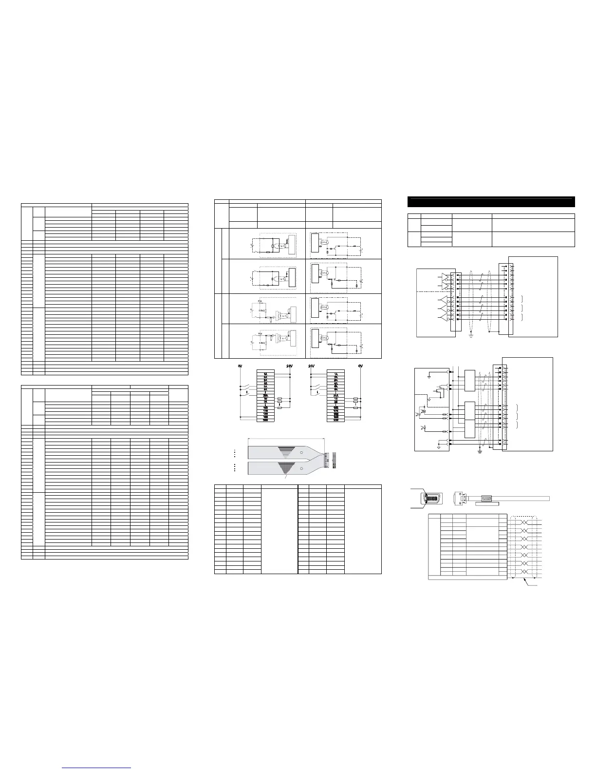
PIO Input and Output Interface
Input section Output section
Input voltage
24V DC±10%
Load voltage 24V DC
Input current 4mA 1 circuit :
Peak load electric
current
SCON-C/CA :
100mA/1 point, 400mA/(Load current total)
SCON-CAL/CGAL :
50mA/1 point, 400mA/(Load current total)
Specifi -c a
tion
ON/OFF voltage
ON voltage MIN. 18V DC
OFF voltage MAX. 6V DC
Leak Current MAX.0.1mA/1 point
N
P
N
Controller
Internal
Power Supply
P24
Input Terminal
680Ω
5.6kΩ
External
Power Supply
24V DC
±10%
Controller
10Ω
N
Output Terminal
External
Power Supply
24V DC
±10%
Internal
Power Supply
Load
P24
SCON-CA/CAL/CGAL
P
N
P
Controller
Internal
Power Supply
Input Terminal
680Ω
5.6kΩ
External
Power Supply
24V DC
±10%
N
Controller
P24
10Ω
N
External
Power Supply
24V DC
±10%
Internal
Power Supply
⽶⩄
Output Terminal
NPN Specification PNP Specification
I/O Cable
Model : CB-PAC-PIO□□□
(Enter the cable length (L) in □□□ Example. 020 = 2m)
No. Signal Name Cable Color Wiring No. Signal Name Cable Color Wiring
1A 24V BR-1 1B OUT0 BR-3
2A 24V RD-1 2B OUT1 RD-3
3A − OR-1 3B OUT2 OR-3
4A − YW -1 4B OUT3 YW-3
5A IN0 GN-1 5B OUT4 GN-3
6A IN1 BL-1 6B OUT5 BL-3
7A IN2 PL-1 7B OUT6 PL-3
8A IN3 GY-1 8B OUT7 GY-3
9A IN4 WT-1 9B OUT8 WT-3
10A IN5 BK-1 10B OUT9 BK-3
11A IN6 BR-2 11B O UT10 B R-4
12A IN7 RD-2 12B OUT11 RD-4
13A IN8 OR-2 13B OUT12 OR-4
14A IN9 YW-2 14B OUT13 YW-4
15A IN10 GN-2 15B OUT14 GN-4
16A IN11 BL-2 16B OUT15 BL-4
17A IN12 PL-2 17B − PL-4
18A IN13 GY-2 18B − GY-4
19A IN14 WT-2 19B 0V WT-4
20A IN15 BK-2
Flat Cable
○
A
(Insulation-Displacement
Connectors)
AWG28
20B 0V BK-4
Flat Cable
○
B
(Insulation-Displacement
Connectors)
AWG28
Operation in Pulse Train Control Mode (Only for SCON-C/CA)
Pulse Train Input and Output Interface
Category
Abbreviated Code Signal Name Contents of Functions
PP, /PP
Input
NP, /NP
Command Pulse Input
Inputs the command pulse train.
Input pulse frequency differs depending on the type.
[Refer to Basic Specifications]
AFB, /AFB
BFB, /BFB
Output
ZFB, /ZFB
Feedback Pulse Output
Outputs the feedback pulse train.
Input pulse frequency differs depending on the type.
[Refer to Basic Specifications]
● When Host Unit is Differential System
● When Host Unit is Open Collector System
AK-04 (option) is required for pulse train input. JM-08 (option) is required for pulse train output.
Only the plug and the shell are equipped for the standard type. [Refer to Product Check Section.]
Perform the same cable layout as the optional connector cable for the pulse train control.
Pin assignment should be the same.
● Option : Cable with Connectors for Pulse Train Control
Model : CB-SC-PIOS□□□ (Enter the cable length in □□□ Example. 010 = 1m)
Pin No.
Pin No.
Load
Load
Flat Cable (20-core)
×
2
BK-4
BR-3
BK-2
BR-1
Open-ended
Open-ended
20A 20B
1A 1B
Half Pitch MIL Socket
HIF6-40D-1.27R (manufactured by Hirose)
A
B
L
Pin No. 1
Pin No. 8
Plug : 10114-3000PE (Sumitomo 3M)
Shell : 10314-52FO-008 (Sumitomo 3M)
CB-SC-PIOS***
Wiring Color
Abbreviated
Code
Signal Name
No.
0.2sq
Soldered
BK
WT/BK
RD
WT/RD
GN
WT/GN
YW
WT/YW
BR
WT/BR
WT/BL
GY
WT/GY
−
−
PP
/PP
NP
/NP
AFB
/AFB
BFB
/BFB
/ZFB
GND
GND
BL
ZFB
−
Pulse Train Input
+
A
−
A
+
B
−
B
+
Z
−
Z
Line Driver Output Line
for Feedback Pulse Output
1
2
3
4
5
6
7
8
9
10
11
12
13
14
Shield is connected to the cable clamp
Host System Side
Shield
Host Unit
Pulse Command
(Line Driver
: 26C31 or equiv.)
(Line Receiver
: 26C32 or equiv.)
Positioning Unit
Counter Unit
CB-SC-PIOS□□□
1
2
3
4
5
6
7
8
9
10
11
12
SCON
PULSE
Connector for Pulse Train Control
NC
NC
PP
/PP
NP
/NP
AFB
/AFB
BFB
/BFB
ZFB
/ZFB
A-Phase Feedback Pulse
Z
-Phase Feedback Pulse
B
-Phase Feedback Pulse
Cable Clamp
Class D grounding
(Formerly Class-III grounding: Grounding resistance at 100
Ω
or less)
1
2
3
4
5
6
7
8
9
10
11
12
13
14
0V
Host Unit
SCON
NC
NC
PP
/PP
NP
/NP
0V
0V
Cable Clamp
0V 24V DC
Pulse
Command
Pulse
Converter
AK-04
(option)
1
2
3
4
1
2
3
4
1
1
2
2
4
33
4
1
1
22
4
33
4
AFB
/AFB
BFB
/BFB
ZFB
/ZFB
PULSE
Connector for Pulse Train Control
CB-SC-
PIOS□□□
A
-Phase Feedback Pulse
B
-Phase Feedback Pulse
Z
-Phase Feedback Pulse
0V
0V
24V DC
24V DC
PP
NP
/NP
/PP
24V
0V
PP
NP
24V
0V
PP
NP
PP
NP
/NP
/PP
PP
NP
/NP
/PP
24V
0V
PP
NP
Counter Unit
Pulse
Converter
JM-08
(option)
Class D grounding
(Formerly Class-III grounding: Grounding resistance at 100
Ω
or less)
*1 It is invalid before home-return operation.
*2 Onl

 Loading...


