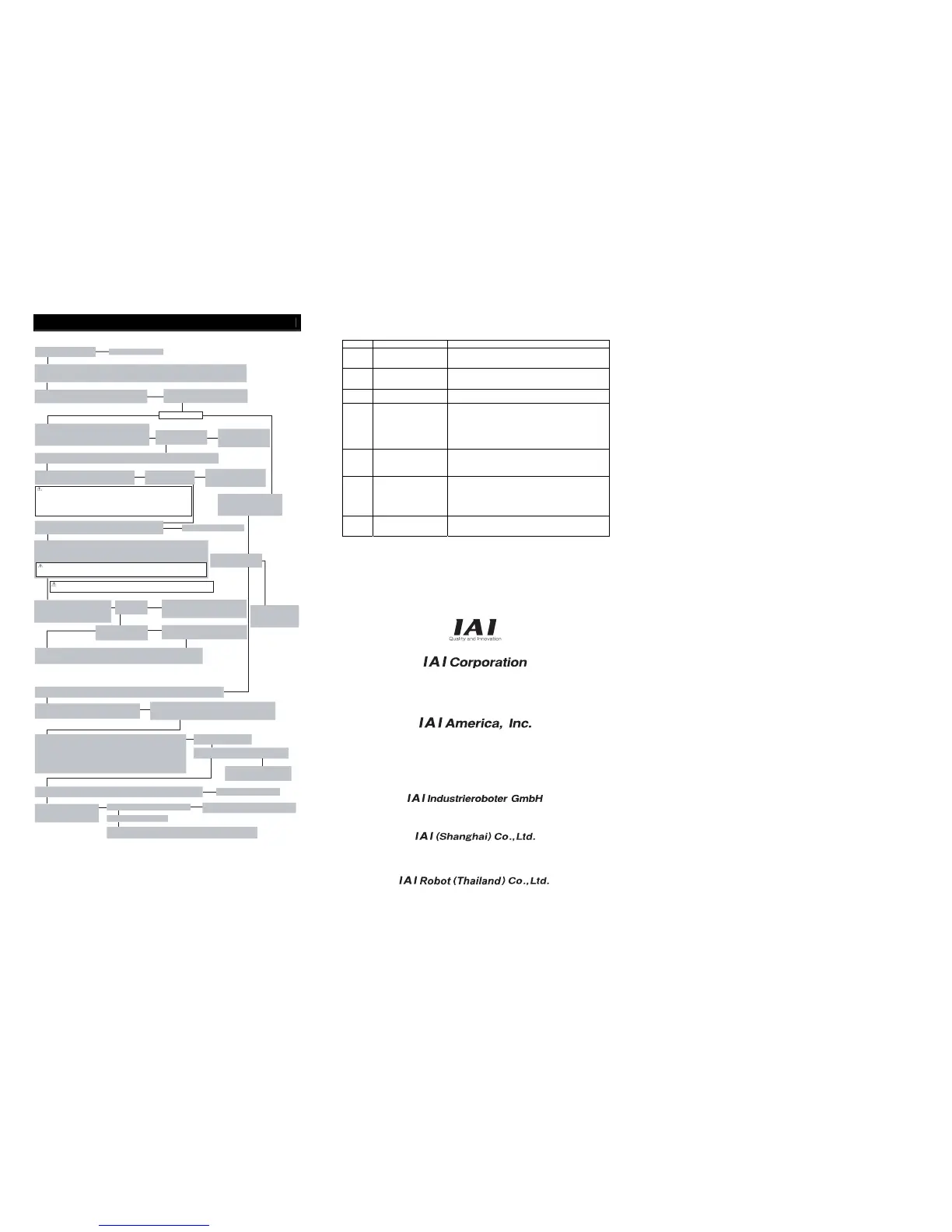
Starting Procedures
When using this product for the first time, make sure to avoid mistakes and incorrect wiring by referring to
the procedure below. “PC” stated in this section means “PC software”.
● Action to Take When Error Occurred
Shown below are the alarms that you may often see after power up. Have an appropriate treatment following
the instructions below.
Please refer to the Instruction Manual for other alarms.
Error Code Error Description Cause and Treatment
069
Real Time Clock Operation
Stop Detection
It indicates the calendar function has stopped and the current
time data has lost. Have the clock settings again from the
teaching tool.
0A5
Electromagnetic Brake
Release Failure Error
Brake could not be released for the electromagnetic brake
equipped type.
Check the 24V power supply for electromagnetic brake.
0CF I/O 24V Power Supply Error
An error is occurred in 24V power supply for PIO.
Check the voltage of the 24V power supply for PIO.
0E5 Encoder Receive Error
This error code appears when the right signal was not received
from the encoder side to the controller command. Check if any
wire breakage on a connector and the condition of wire
connections. If no error is generated under the condition that the
power to all the peripheral equipment is shut and operate only
this controller and the actuator, noise can be considered as the
cause of the problem.
0E7
A-, B- and Z-Phases
Breakage Error
It is the condition that the encoder signal is not properly
detected.
Check if any wire breakage on a connector and the condition of
wire connections.
0EE
Absolute Encoder Error
Detection 2
This error code appears when the absolute encoder PCB cannot
detect the position information properly. The voltage for the
absolute data battery is dropped. Check the battery alarm output
on PIO, and if it is off, replace the battery. Perform Absolute
Reset after the replacement.
Check the encoder cable connection.
20A Servo Off While in Operation
It shows the operation command was generated in the condition
that the servo is off.
Resume the operation after turning the servo on.
Head Office: 577-1 Obane Shimizu-KU Shizuoka City Shizuoka 424-0103, Japan
TEL +81-54-364-5105 FAX +81-54-364-2589
website: www.iai-robot.co.jp/
Ober der Röth 4, D-65824 Schwalbach am Taunus, Germany
TEL 06196-88950 FAX 06196-889524
SHANGHAI JIAHUA BUSINESS CENTER A8-303, 808, Hongqiao Rd. Shanghai 200030, China
TEL 021-6448-4753 FAX 021-6448-3992
website: www.iai-robot.com
Technical Support available in USA, Europe and China
Head Office: 2690 W. 237th Street, Torrance, CA 90505
TEL (310) 891-6015 FAX (310) 891-0815
Chicago Office: 1261 Hamilton Parkway, Itasca, IL 60143
TEL (630) 467-9900 FAX (630) 467-9912
TEL (678) 354-9470 FAX (678) 354-9471
website: www.intelligentactuator.com
Atlanta Office: 1220 Kennestone Circle, Suite 108, Marietta, GA 30066
825 PhairojKijja Tower 12th Floor, Bangna-Trad RD., Bangna, Bangna, Bangkok 10260, Thailand
TEL +66-2-361-4458 FAX +66-2-361-4456
Manual No.: ME0202-7A
→
No
→
→
No
→
↓
Ye s
No
→
→
Check the emergency stop circuit.
→
No
→
↓
Ye s
↓
Ye s
↓
Ye s
↓
No
↓
Ye s
↓
↓
Yes
→
No
→
Yes
→
Ye s
Check of Packed Items
Are there all the delivered items?
Please contact the distributor.
Point Check Item
• Is frame ground (FG) connected?
• Has the noise countermeasure been taken?
Power Supply and Alarm Check
Connect a teaching tool such as PC, turn the mode changeover
switch to “MANU” side and turn the power on for each unit.
Select [Teaching Mode 1 Safety Speed Activated / PIO
Operation Invalid] in the teaching tool such as PC.
Check Item
Is the orange light [ALM] on
the LED status display off?
Connect the PC or teaching
pendant and check the
content of the alarm to have
the right treatment.
Select Operation Mode
Positioner Mode Pulse Train Mode
Safety Speed Setting
Set it in Parameter No. 35 if necessary. The safety speed is set to 100mm/s at the delivery.
Servo
ON
Turn the servo on with the operation on the teaching
tool such as PC.
Check Item
Is the green light [SV] on
the LED status display on?
Pulse Train Mode Startup
Turn off the power to the controller.
Turn on the pulse train mode
changeover switch 1, and then turn
on the power to the controller.
Check Item
Is the orange light [ALM] on
the LED status display off?
Connect the teaching
tool such as PC to confirm
the content of alarm and
have an appropriate
treatment.
If an alarm is generated, connect
the PC or teaching pendant and
check the content of the alarm to
have the right treatment.
CAUTION
Please perform this process with the actuator away from the mechanical end or
interfering subjects as much as possible.
Put the actuator away if it interferes with surroundings. It may generate an alarm if the
actuator hit the mechanical end or interfering subjects when the servo is turned on.
The slider may get slightly dropped by self-weight if servo on and off is repeatedly
performed at the same position. Be careful not to pinch the hand or damage the work.
Safety Circuit Check
Does the emergency stop circuit (drive cutoff circuit) work properly and
turn the servo off?
Target Position Setting
Set the target position in “Position” Box in each position table.
Perform a home-return operation first when Direct Teaching is to be performed. When moving the
actuator manually, set the Brake Release Switch to “BK RLS” side for the brake equipped type.
Put the switch back after the setting is complete.
CAUTION
To ensure safety, it is recommended that safety speed be enabled during initial movements.
Check Item
Any vibration or
abnormal noise?
Check Item
Use the force control
(function for CA Type only)?
Check the actuator if it is installed properly,
the condition for use is below the rated values,
etc.
Adjust the servo if necessary.
Initial Setting for Force Control
Perform the initial settings such as the loadcell
calibration on the teaching tool.
Test Run Adjustment 1
Check the operation without mounting
a work and set the safety speed invalid
on the teaching tool such as PC, and then
check the operation with a work mounted.
Test Run Adjustment
2
1) Turn the operation mode setting switch to “AUTO” side.
2) Output the operation command from PLC to the controller and check the system operation.
Safety Speed Setting
The safety speed is set to 100mm/s at the delivery. Change the setting in Parameter No. 35 if needed.
Electronic Gear Setting
Set the electronic gear ratio based on the amount of
actuator operation per pulse in Parameters No. 65 and 66.
↓
→
Check Item
Is the minimum unit of operation set to the value bigger than the
minimum resolution of the encoder?
Is the fraction of the electronic gear ratio reduced to its lowest terms?
↓
Ye s
↓
No
Pulse Train I/O Mode Setting
Set the command pulse train input form to Parameters No. 63 and 64 for the input.
[Items Selected in Pulse Train Input Form]
Active high and active low
Forward pulse train, reverse pulse train, pulse train, forward/reverse code,
A- and B-phase pulse trains
Set the feedback pulse train output form to Parameters No. 68 and 69 for the output.
[Items Selected in Feedback Pulse Train Output Form]
Feedback pulse output, feedback pulse form, polarity of feedback pulse form
Servo
ON
Input servo on signal from PLC
Check Item
Is the green light [SV] on the LED status display on?
→
Confirm the content of alarm on the
teaching tool such as PC to have an
appropriate treatment.
↓
Ye s
Safety Circuit Check
Confirm the emergency stop circuit (drive cutoff circuit) works properly and turns the servo off.
Check the emergency stop circuit.
No
→
Test Run Adjustment
Output the pulse train from PLC to
controller and check the system
operation.
→
No
→
↓
Ye s
Check the electronic gear ratio setting.
Check the command pulse train input mode setting.
Any vibration or abnormal noise?
Yes
Check if the actuator is installed properly, the condition for the actuator use is below
the rated values, or the right pulse train input is done, etc.
↓
Ye s
Installation and Wiring
Install and wire the actuator and the controller following the
instructions described in the Instruction Manual and this guide.
Initial Operation Check
Connect our controller to the actuator.
Connect a teaching tool such as PC, set the operation mode setting switch to “MANU” side and turn the power on.
Confirm the operation by performing a home-return operation and jog operation in full stroke range on the teaching tool.
↓
No
↓
↓
CAUTION
Be careful not to pinch the hand or damage the mechanical hand by the slider dropped with the
self-weight when turning the brake release switch to “BK RLS” side if it is mounted vertically.
Does the positioning operation work properly?
(Only for SCON-C/CA)

 Loading...


