INSTALLATION AND OPERATION INSTRUCTIONS
1-32
DC SERIES COMBI BOILERS DC 23-84, DC 29-106, DC 33-124, DC 33-160
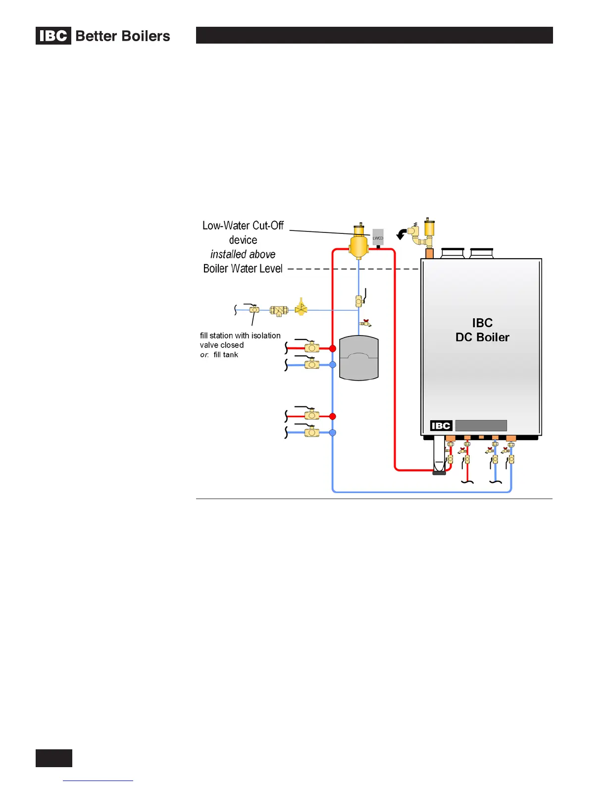
EXTERNAL LOW WATER CUT OFF DEVICE
DC Series Boiler Only - An external low water cut-off device is not required if the
boiler is only being used as a direct domestic hot water unit.
If an external low water cut-off device is required, an electronic probe style device
is recommended.
• The low water cut-off device must be installed in the boiler supply water
piping, with a tee connection, at a level above the top of the boiler.
• The low water cut-off device must be wired in series with the 120Vac power
supply so that when the device trips on a low water condition the power
supply to the boiler is interrupted.
1.9.2 Power Quality and Electrical Protection
In areas of unreliable power, appropriate surge protectors and or power
conditioning equipment should be installed to protect the boiler.
1.9.3 Zone Valve and Zone Pump Connections
Zoning can be accomplished with either zone pumps or zone valves. In either
case the controls and relays that may be required to accomplish this will need to
be installed externally.
Zone Valve end switches can be wired to together in parallel and connected to
a fan center relay. See Figure 35. Do not apply power to the X4 terminal strip.
Alternately the zone valves and thermostats can be connected to a zoning panel
control system available from your local heating wholesaler.
Zone Pumps can be connected to the boiler with a zone pump control available
from your local heating wholesaler.
Figure 34: External Low Water Cut Off Device