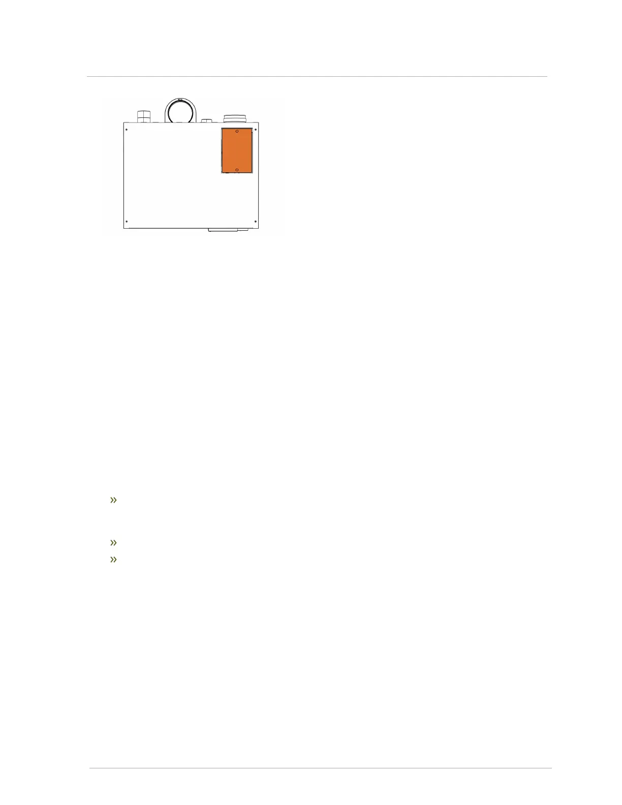
Figure 25 Filter door - top view of boiler
3.6 Installing a condensate trap
IBC’s specified vent configuration promotes the safe drainage of moisture from the boiler and exhaust
venting without flowing liquids back through the heat exchanger (as done by some other condensing
boilers).
Reliable system operation requires:
1. Proper design and installation of exhaust venting to allow condensate to run back to the
drain/trap.
2. Acid neutralization as appropriate.
To achieve these:
Allow a minimum ¼" per foot slope back to the vent connection, with appropriate hangers to
maintain that gradient. For PPs venting, follow the manufacturer's requirements. This will
ensure proper drainage and prevent condensate from clogging.
Ensure the supplied trap is correctly installed and filled with water.
When required, add (and maintain in good condition) a neutralization tank. For information on
installing a condensate neutralizer, see Installing a condensate neutralizer on page 39.
The condensate trap must be installed on the drain connection at the base of the boiler. The
condensate drain must be piped to within 1" of a drain or connected to a condensate pump. The
drainage line must slope down to the drain at a pitch of ¼" per foot so condensate runs towards the
drain.
3.6 Installing a condensate trap