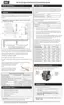
Pressure relief valve (shipped with boiler): no isolation valve is permitted between the boiler
and relief valve.
Tridicator or external pressure and temperature gauge (shipped with boiler).
Hydraulic separator (low-loss header) provides primary/secondary hydraulic separation, a
microbubble air eliminator and a dirt separator. Air eliminator is installed at the most
effective point, where the fluid is at the highest temperature and lowest pressure.
Secondary pumps to multiple loads or zones. All receive identical temperatures. Note
integrated check valves.
Return lines from loads.
Expansion tank connection (point of no pressure change)should be on the suction side of
the circulator.
Primary pump or boiler circulator into connection at rear of boiler.
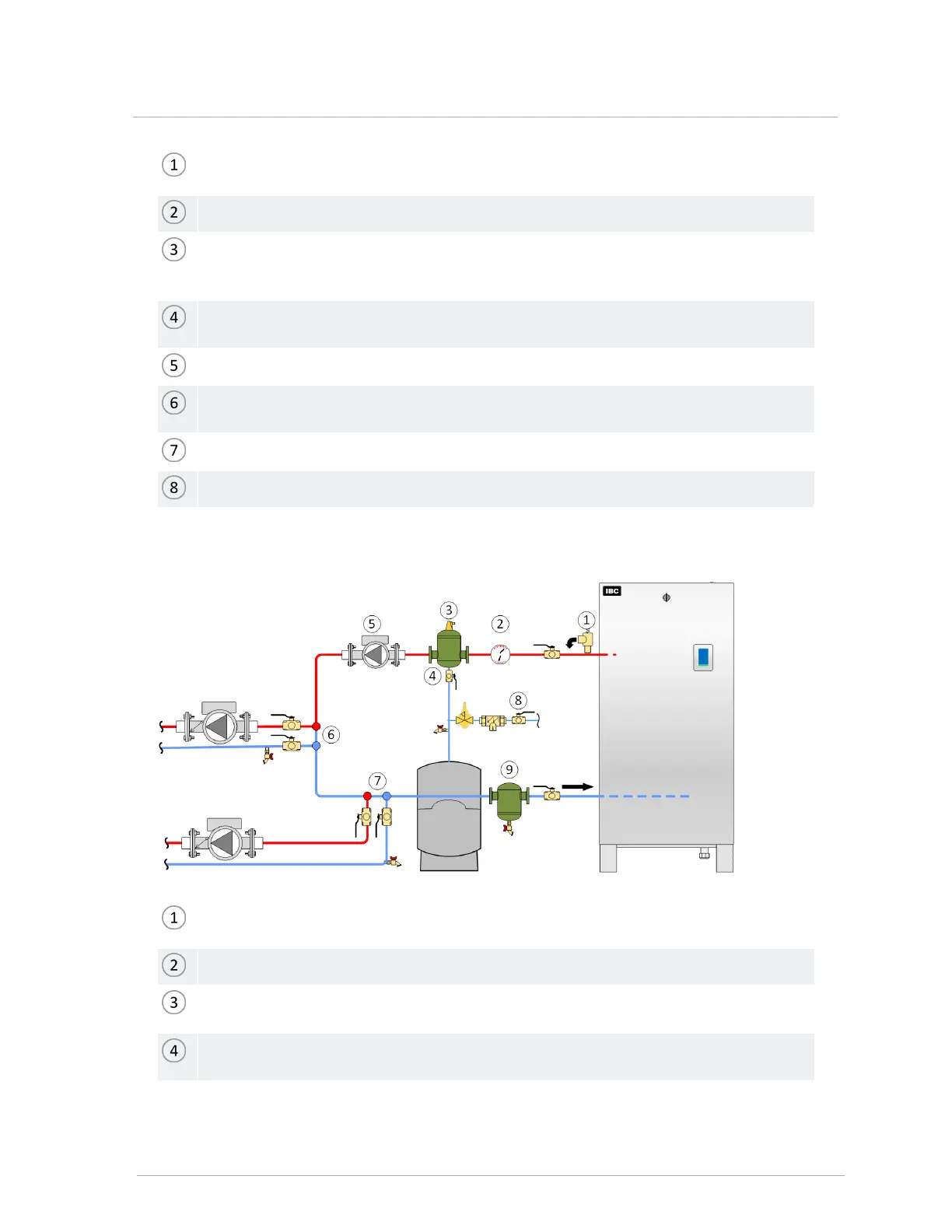
Fill station with isolation valve closed, or fill tank.
Pressure relief valve (field-supplied): no isolation valve is permitted between the boiler and
relief valve.
Tridicator or external pressure and temperature gauge (field-supplied).
Microbubble air eliminators are best installed where the fluid is at the highest temperature
and lowest pressure.
Expansion tank connection (point of no pressure change) should be on the suction side of
the circulator.