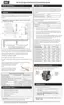
Figure 54 Connector wires
5.
Gently remove the silicone air pressure tube from the gas valve by gripping near its base,
and put aside.
Figure 55 Silicone air pressure tube
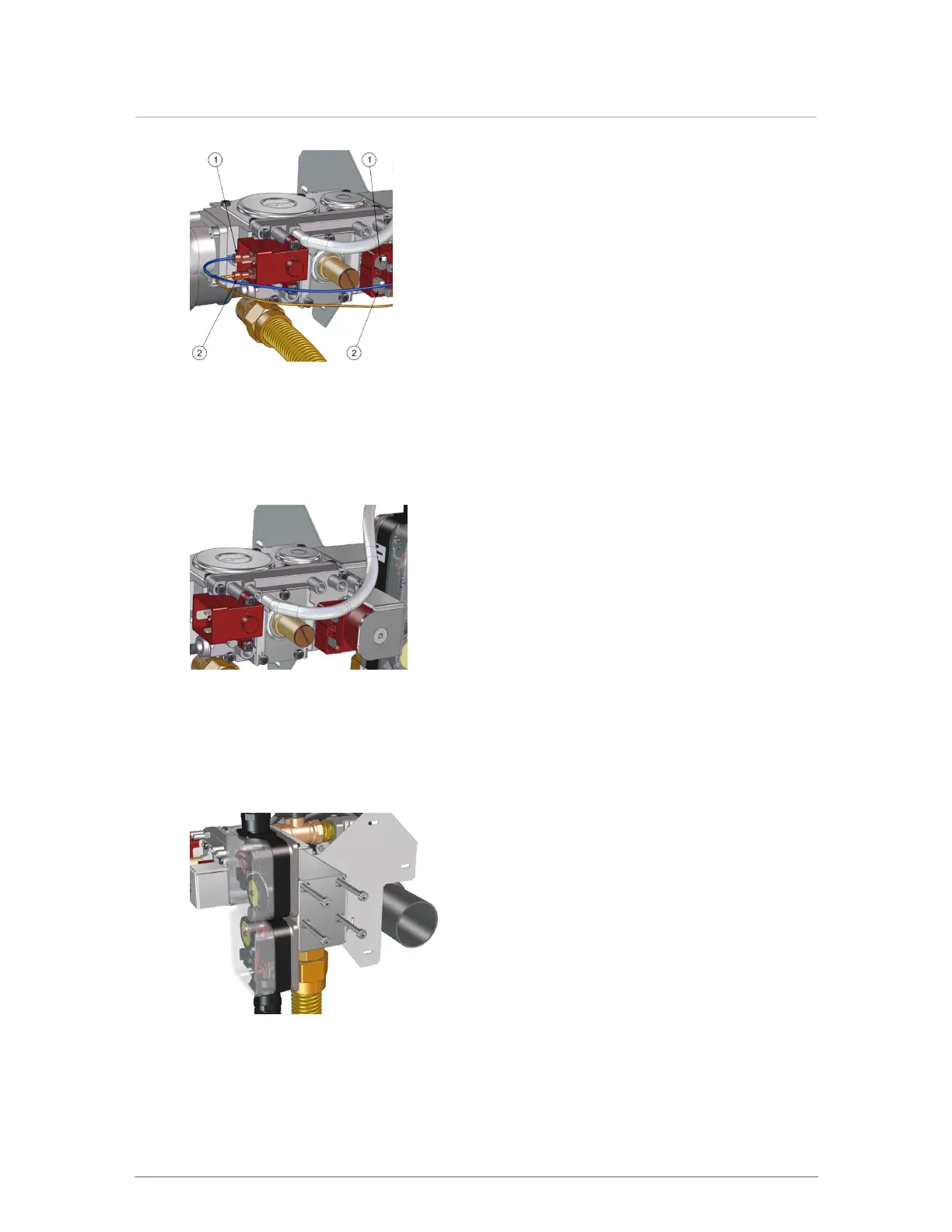
6.
From the inlet side of the gas valve (see on Figure 51 ), remove the four (4) screws using
a 4mm Allen key, and put aside.
Figure 56 Screws on gas valve inlet
Section: Service and maintenance