INSTALLATION AND OPERATION INSTRUCTIONS
6-2
SFC COMBI BOILERS SFC-99, SFC-125
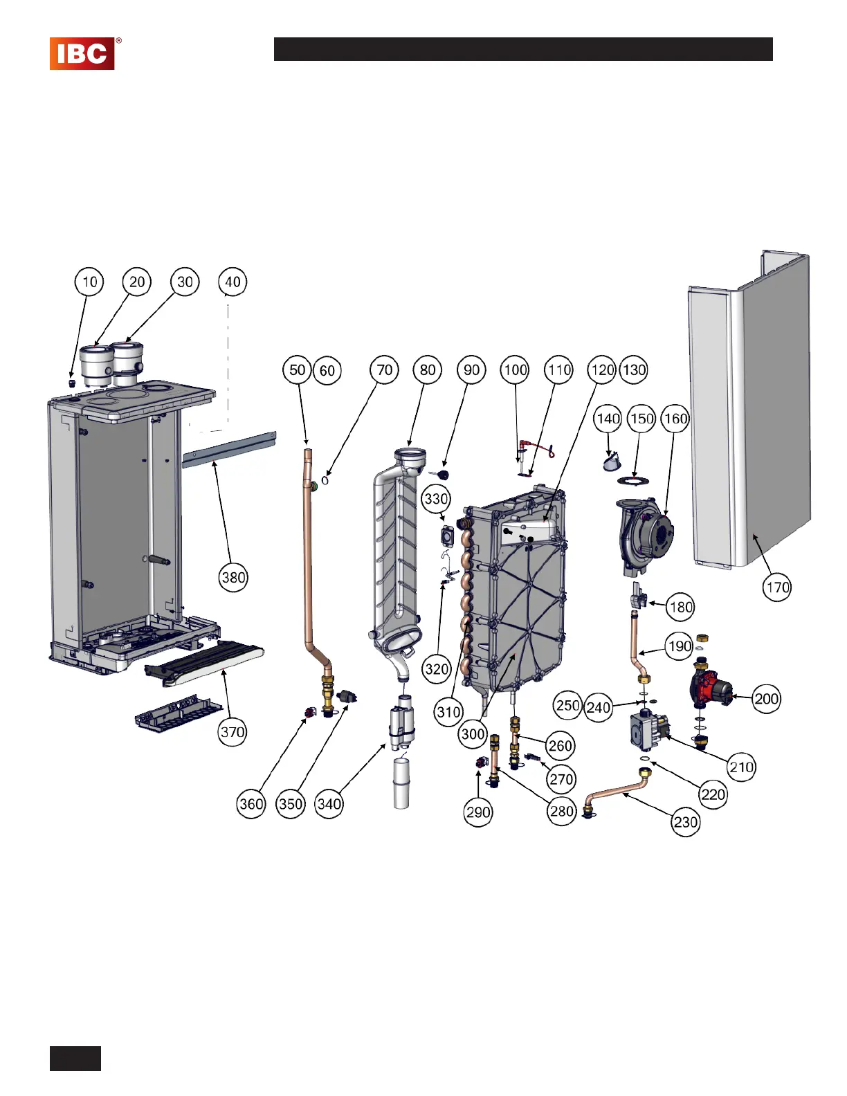
6.1 PARTS DIAGRAMS
Diagram 6.1-1: Unit assembly parts
SFC Series modulating unit - Parts assembly
For information on the contents of P-kits, visit the Technical Information portal at www.ibcboiler.com.