6-3
DIAGRAMS
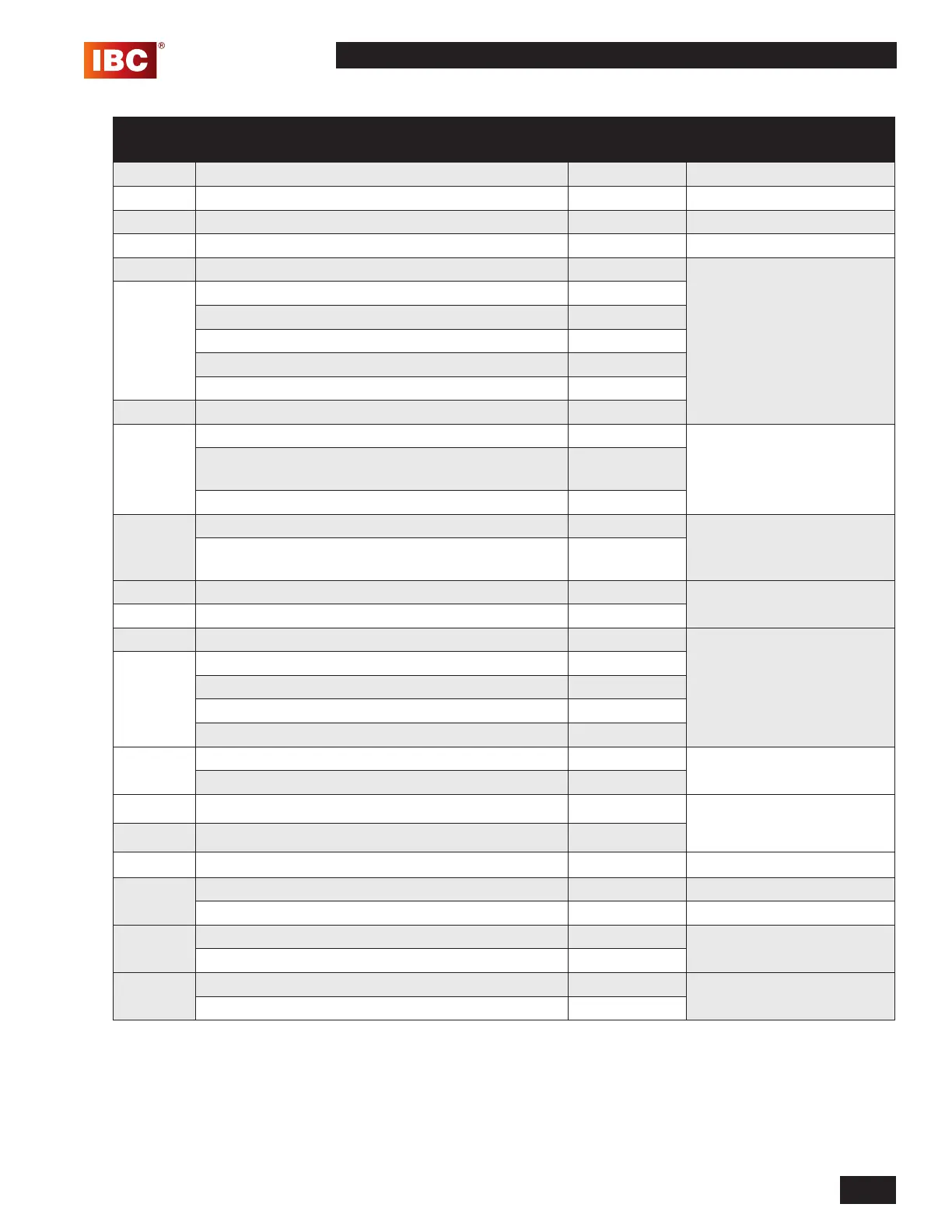
SFC COMBI BOILERS SFC-99, SFC-125
BOM ID Part Description Part # Replacement Kit
Numbers
10 Manual air vent 180-227 P-808
20 Combustion air intake tting and screen 250-776A1 P-809
30 Flue exhaust tting 250-775A1 P-810
40 Ignition module 180-202 P-811
50 Boiler supply water pipe 180-240 P-812
60 - tting supply tube 180-234
- Fitting UNF 7/8"x 22mm 180-235
- Nut spring clamp 22mm 180-236
- Spring clamp 22mm 180-237
*- O-ring 22.3x2.4 EPDM70 180-238
70 *Supply water pipe gasket 250-635
80 Rear ue duct 251-136 P-889
Flue / Heat EX Gasket 150-312
Flue Pipe Outlet Gasket 150-313
90 Flue gas temperature sensor 180-205 P-814
*NTC shaft 1/8” SW15 150-314
100 Ignitor and cable 240-115 P-815
110 *Ignitor gasket 250-622A1
120 Burner 180-114 P-712
130 *Burner gasket 250-646A1
Screws x 4 150-344
Spring 150-241
O-ring 150-343
140 Backow valve 180-178 P-817
*Backow valve apper (viton) 180-184
150 *Fan gasket 250-627A1 P-818
160 Fan 240-120
170 Front panel assembly 99/125 180-262 P-886
180 Venturi insert SFC 99 # 528 180-132 P-820
Venturi insert SFC 125 # 500 180-133 P-821
190 Gas line (gas valve to fan) 180-210 P-822
Gas line O-ring 150-245
200 Boiler pump, SFC 180-130 P-823
*Pump gasket x 2 -
* See next page for gasket package for SFC-99/125; includes all gaskets asterisked above