3
SL 45-260
PROPANE CONVERSION PARTS KIT# P
-
170B
120-166 R2
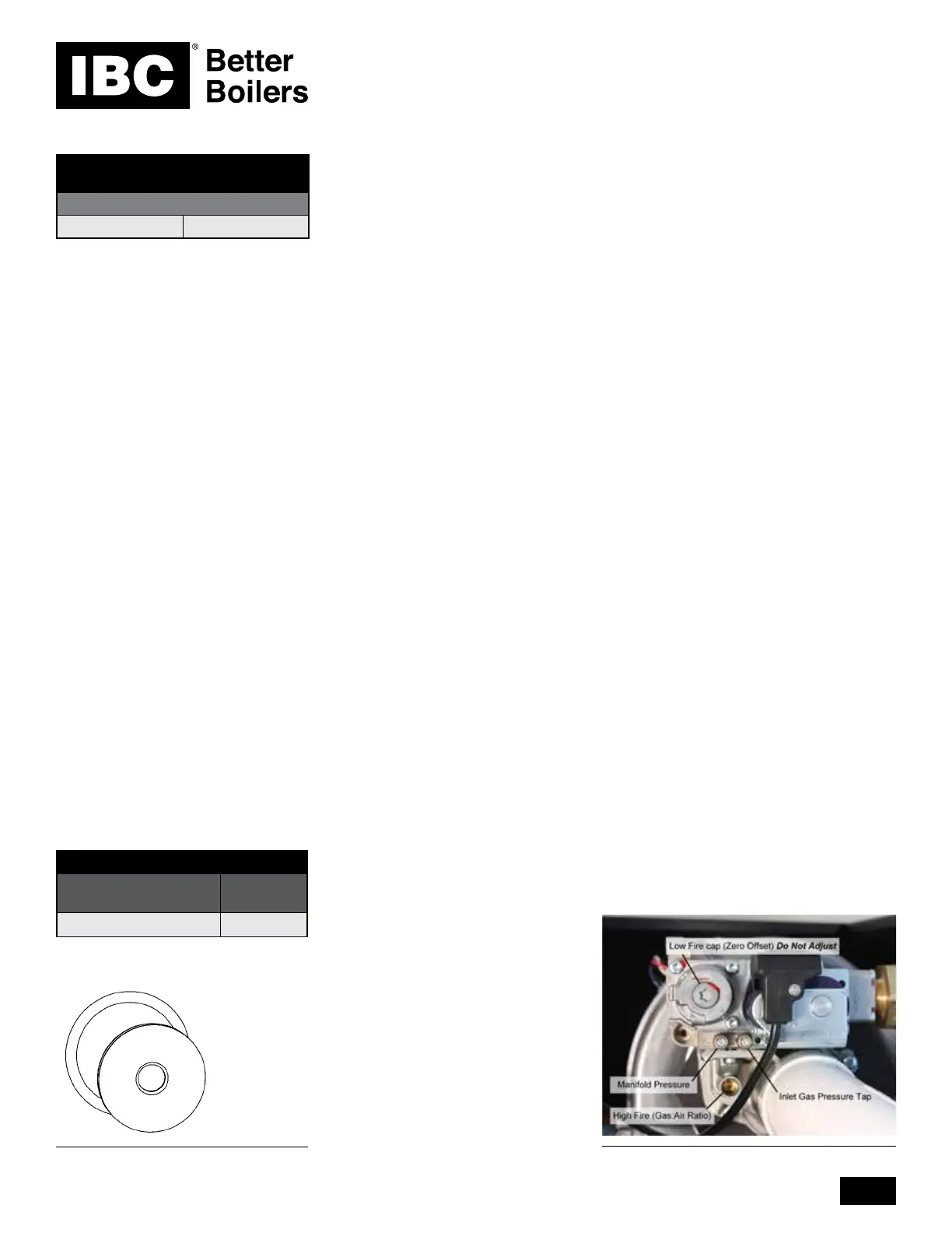
Combustion Testing and Adjustment
To verify the proper operation of the gas valve in the eld, the following procedure
can be carried out by a qualied technician (diagrams on this page).
Normal ignition system sequence of operation: The boiler control, upon a call
for heat or DHW, will turn on the combustion fan for a 20 second pre-purge, then
energize the spark electrode and gas valve for a 4 second trial for ignition. If the
burner does not light and prove ame, the process is repeated until the burner
lights and ame is detected or after 3 trials for ignition the boiler will lock out and
will need to be manually reset by clearing the error. The boiler will automatically
reset after 60 minutes if no action is taken.
1. Turn o the boiler’s gas shut o valve. With a small (1/8” or 3 mm) at
screwdriver, open the inlet gas supply pressure test port by turning its center-
screw 1 full turn counterclockwise. Attach a manometer to the pressure test
port and turn on gas to appliance. Static manometer reading should be ideally
7” w.c., for Natural Gas and 11” w.c. for Propane. Minimum and maximum
static pressure should be between 5” and 14” w.c. Monitor pressure throughout
the comissioning procedure. Pressure may droop up to 1” to 2” w.c. at high
re. Outlet Pressure (Manifold Pressure) should be between -0.04” w.c. and
0.00” w.c. with a target of -0.02” w.c. NOTE: The outlet pressure should
only be measured with an accurate digital manometer. Consult factory before
considering eld adjustment.
2. Set a load as manual control and run the boiler at 260MBH. This load should
be large enough to allow the boiler to operate at high re for 10 plus minutes.
Take note of what the load was set for before you change it to manual control.
3. Turn the High Fire (Gas : Air Ratio Adjustment) screw 1-1/4 turns clockwise
using a 2.5mm hex key.
4. With a combustion analyzer probe in the ue gas test port, turn the High Fire
(Gas : Air Ratio Adjustment) screw clockwise
(see diagrams on this page) to
achieve results. This screw oers very ne adjustment, and may require several
turns. Turning the High Fire (Gas : Air Ratio Adjustment) screw clockwise will
lean out the ame. NOTE: Clock the gas meter to conrm full maximum rating
plate input. Check the measured results with Table 3 - High Fire.
5. Set the heat out value in manual mode to 45MBH.
6. While the boiler is at Low Fire, compare the combustion reading against the
readings in Table 2. The readings should be within the range listed in Table 2.
7. Restore the load to the previous load type. All the programmed settings will
be restored and the load will operate as it was previously. Conrm a smooth
ignition sequence.
8. Turn o the gas supply at
the gas shut o valve and
disconnect the power to
the boiler. Disconnect the
manometer. Close the gas
supply test port screw by
turning clockwise. Turn on the
gas supply shut o valve and
test for gas leaks. Restore
power to the boiler.
Orice and O-ring
PROPANE ORIFICE CHART
MODEL
NUMBER
ORIFICE
SIZE
SL 45-260 6.8 mm
MODEL
NUMBER
HIGH FIRE
INPUT
NATURAL GAS OR PROPANE
SL 45-260 260 MBH
Table 3: Rated input of a converted boiler
Clocking the Meter
(Natural Gas)
1. Turn o all other appliances and
pilots
2. Turn on the boiler and set the
boiler to high re. Ensure the
boiler has a large load to heat so
that the boiler will not shut o.
3. With a Stop-Watch, record
the number of seconds for the
smallest dial to make 1 full
revolution.
4. CFH = (3600 x Dial Size) /
Seconds
5. CFH x 1000 (check local Btu
content) = Input Btu’s
NOTE:
• For 2 PSI meters multiply CFH x
1.097
• For Metric meters multiply CFH x
35.3
• For 2 PSI metric meters multiply
CFH x 1.097 x 35.3
• For Altitude above 4,500’ deduct
2% per 1,000' of altitude from the
Input Btu’s
Gas Valve Adjust

 Loading...


