2
SL 45-260
PROPANE CONVERSION PARTS KIT# P
-
170B
120-166 R2
Refer to the details in the boiler’s current Installation and Operation Manual,
section 3.3 - “COMMISSIONING”, 3.4 “FUEL CONVERSION”
The Low Fire (Zero-oset) valve adjustment cap on the gas valve has been factory
set. This screw (4mm Hex) must not be tampered with. The Zero-oset
screw is not to be adjusted in the eld. Consult factory for written instructions if
considering eld adjustment of the Low Fire (zero oset) adjustment.
The High Fire (Gas:Air) ratio adjustment screw (2.5mm Hex) will have to be
adjusted to attain optimum combustion results whenever fuel conversion is
undertaken, however, no mixture adjustment shall be performed unless
done by a qualied technician using properly functioning and calibrated
combustion analyzing equipment. The following procedure must be carried out
by a qualied technician:
MODEL HIGH FIRE LOW FIRE CO MAX
PPM
RANGE TARGET RANGE TARGET
SL 35-199
(Natural Gas) CO
2
9.1 – 9.7 9.5 8.4 – 9.0 8.7 150
SL 35-199
(Propane) CO
2
10.5 – 11.1 10.8 9.4 – 10.2 9.8 180
SL 45-260
(Natural Gas) CO
2
9.1 – 9.7 9.5 8.4 – 9.0 8.7 120
SL 45-260
(Propane) CO
2
10.5 – 11.1 10.8 9.4 – 10.2 9.8 150
Table 2: Combustion Test Target Range – CO
2
Fuel Conversion Instructions
The following procedure must be carried out by a qualied technician.
1. Ensure you are installing the correct fuel conversion kit for your boiler.
Compare the boiler model number with the Kit# found in table #1. Ensure you
have the correct Orice by checking the Orice size with the Chart on page 3.
2. Ensure the fuel conversion instructions supplied with the fuel conversion kit are
read, understood and followed carefully.
3. The gas supply shall be shut o prior to disconnecting the electrical power, and
before proceeding with the conversion. Ensure that the gas supply is turned o
at the gas shut o valve.
4. Using a #25 Torx wrench, undo the 3 venturi mounting screws.
5. Lift the gas valve up and away from the venturi.
6. Insert the orice in to the O-ring and re-seat the gas valve on the venturi.
7. Re-install the 3 venturi mounting screws and tighten.
8. Restore gas supply by opening the gas control valve, and using an approved
leak detection solution, soap test all joints.
9. Carefully follow the procedures on page 3, Combustion Testing and Adjustment
10. Place the conversion labels associated with the new fuel onto the boiler at the
positions indicated page 4 of this Instruction Document.
CAUTION
The gas supply shall be shut o
prior to disconnecting the electrical
power, before proceeding with the
conversion.
DANGER
A combustion test must be done
by a qualied, trained and licensed
gas tter in order to complete any
fuel conversion.
Making adjustments to the IBC gas
valve without a properly calibrated
gas combustion analyzer and by
persons who are not trained and
experienced in its use is forbidden.
Failure to use an analyzer can
result in an immediate hazard.
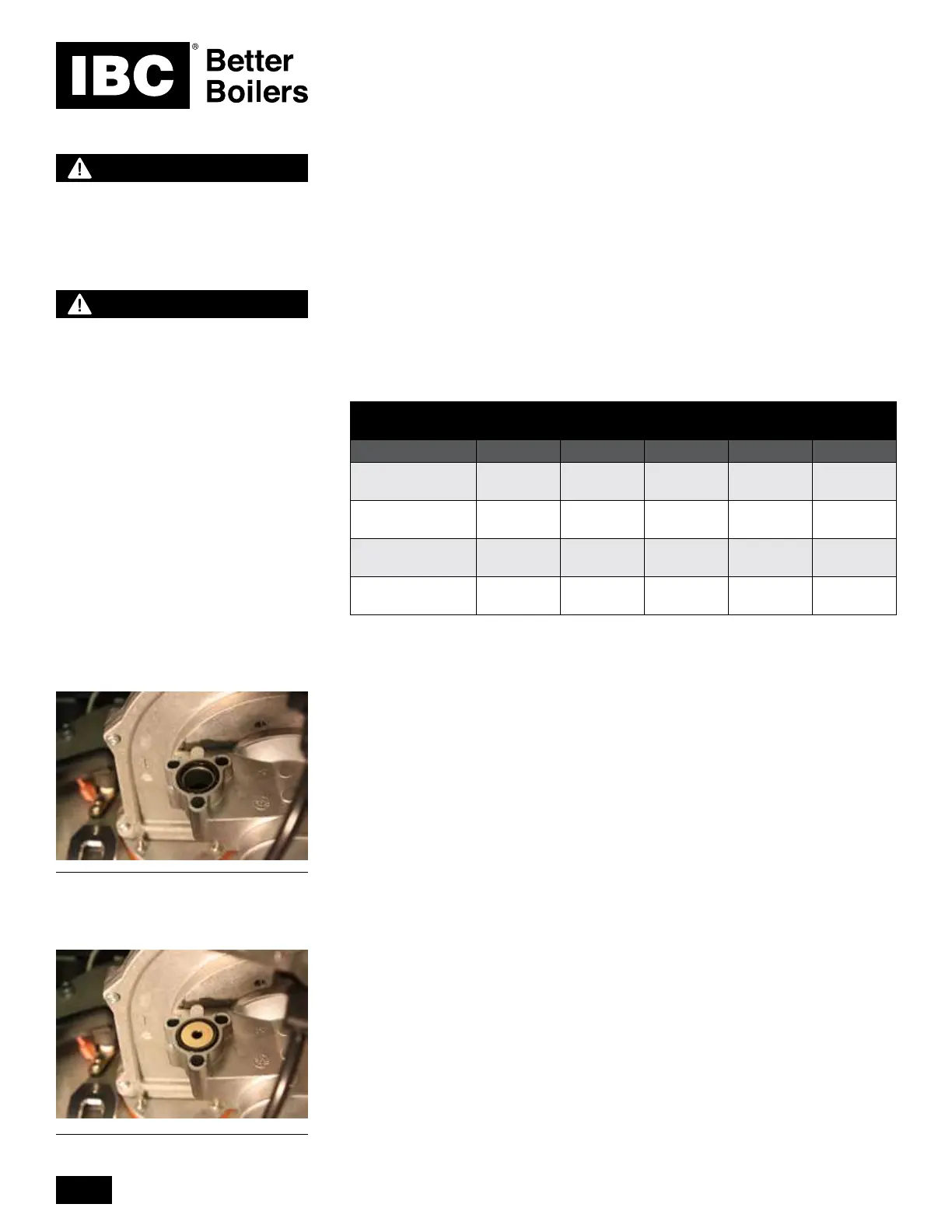
Venturi without an orice in an SL 45-
260 Natural Gas boiler. This Natural
Gas model does not use an orice.
Orice inserted for an SL 45-260 boiler
using Propane.
 Loading...


