41
Version 17.01, as of: 27-Jun-2017
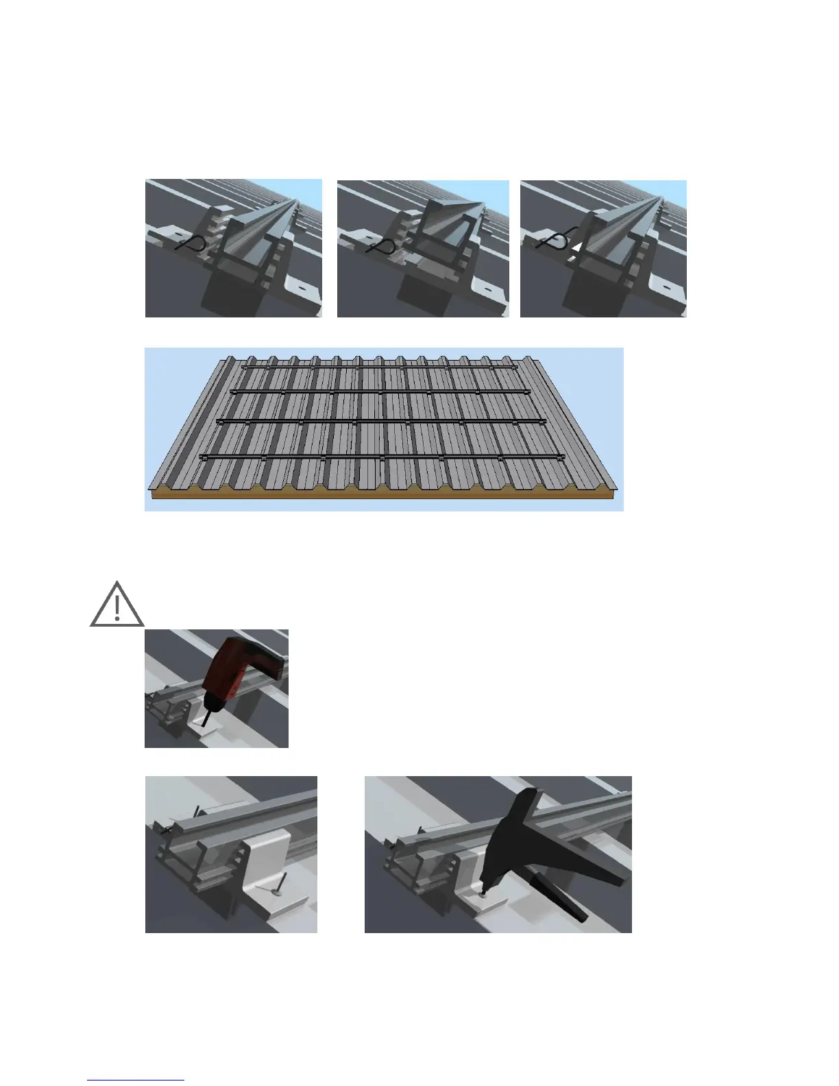
Step 6: Insert and align the TF27-T carrier rail
Figure 60: Insert the carrier rail Figure 61: Align the carrier rail Figure 62: Close the clamp
Step 7A: Affix the TRAPEZOIDAL CLAMP to the outer roofing with blind rivets
Important:
A drill with a diameter of 5.0 mm is mandatory to maintain static properties!
When using the rivets drill two bores with a diameter of 5.0 mm per
TRAPEZOIDAL CLAMP . In this process, make sure you drill carefully to
maintain static properties.
Now insert the 4.8x15mm blind rivets into the bores and rivet.
The enclosed 4.8x15 mm blind rivets are approved for a sheet metal or
aluminium thickness of 0.5 mm to 1.5 mm.
Figure 65: Inserting blind rivets Figure 66: Riveting using a standard rivet head