52
Version 17.01, as of: 27-Jun-2017
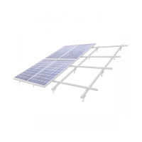
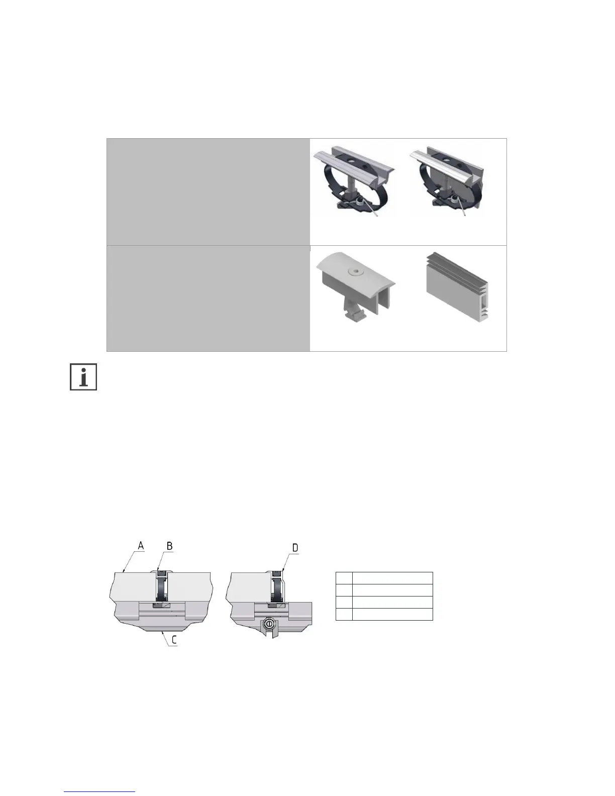
Figure 91 Assembled clamps (sectional view)
The middle and outer clamp are delivered pre-
assembled.
The middle clamp G3 covers a clamping area of
30-50 mm.
However the outer clamp G3 must be ordered for
each module height.
G3 Middle and outside clamp
The middle clamp G4 covers a clamping area of
33-46 mm.
The EC adapter is installed with the middle clamp
G4 or G3 and replaces the traditional outer clamp.
G4 middle clamp and EC adapter
Important information:
Depending on the height of the module frame, a different version of the outer clamp G3 will be required.
The EC adapter for G4 middle clamp covers only the frame sizes 33, 35, 38, 40, 45 and 46mm.
The tightening torque of the clamps must 15 Nm!
Do not use a ratchet or a wrench with high leverage as the maximum tightening torque could easily be
exceeded.
Please only use a Torx screwdriver with T-handle or cordless screwdrivers with the appropriate torque
settings.