3-3
STARTUP AND COMMISSIONING
VFC 15-150 - VFC 45-225 MODULATING GAS BOILERS
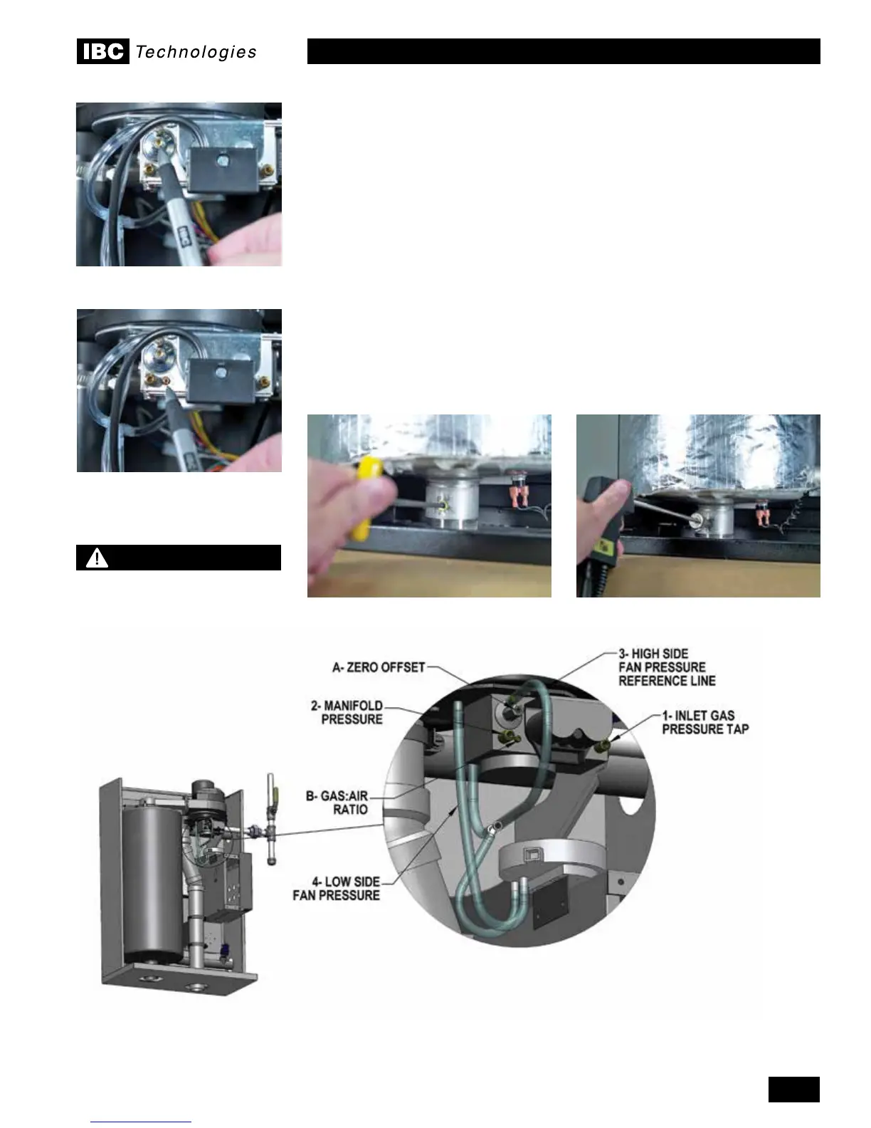
4. Withacombustionanalyzerprobeintheuegastestport,turntheGas:Air
Ratio Adjustment screw (see Figure 31, “B”) to achieve 28% excess air
(corresponding CO2 values are 9.2% for natural gas and 10.4% for propane).
Thisscrewoffersveryneadjustment,andmayrequireseveralturns.
NOTE:Thisscrewhassignicantbacklash.Whenchangingdirectionofturn,
it may take up to a full turn before any change is indicated on the analyzer
reading.Clockthegasmetertoconrmfullmaximumratingplateinput.
5. Toconrmoradjusttheminimumrelevelsettings,Re-denetheloadas
“ManualControl”.UseHeatOutputin“CongureLoadx”tocontroltheoutput
as needed.
6. Attheminimumringrate,adjustthezero-offsetscrew(see Figure 31, “A”)
to obtain 28% excess air. It may be necessary to reduce the output in stages
if this adjustment has been tampered with.
7. Turnboileroffbyremovingthecallforheat(usetheHeatLoadConguration
screen to turn load to off if no other ready means available), then remove the
manometer connections, and turn the centre-screw in the manifold pressure
test port 1 full turn clockwise. Ensure fully closed, but not over-tightened.
Figure 31: Gas Valve and Pressure Reference System
Zero-offset adjustment screw
Gas:Air ratio adjustment screw
Insertion of ue gas analyzer probeRemoval of ue gas test port plug
NOTE
Upon installation of this
boiler, you must use an
indelible marker on the rating
plate to mark an X in the box
associated with the fuel used.
 Loading...


