1-13
INSTALLATION
VFC 15-150 - VFC 45-225 MODULATING GAS BOILERS
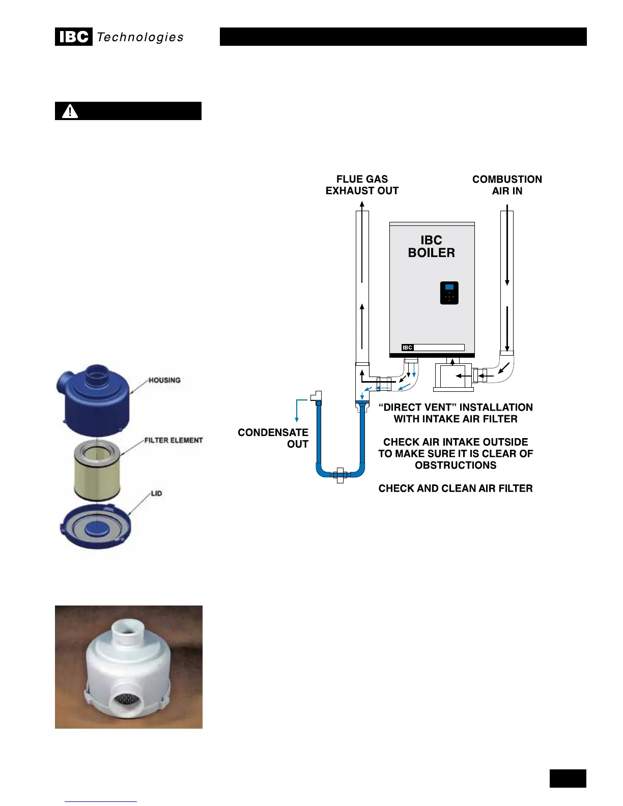
Air intake lter IBC Part # 103
1.4.9 Combustion Air Filtration
If combustion air contamination from ingested particulate matter may be a
concerninanyinstallation,anoptionalairintakeltermaybeinstalled.IBC
suppliedairintakeltershaveaknownpressuredropandfoulingfactorand
should be used as a component of the combustion air system according to the
allowable intake length in Table 4.
1.4.10 Closet Installations
Forinstallationsinaconnedspace(suchasacloset),ventilationopeningsmay
be needed through a door or wall to prevent excessive heat from building up
inside the space.
The boiler shall not be exposed to ambient conditions above 122°F (50°C) or
below 32°F (0°C).
NOTE
Combustion fan
blockages can occur when
environmental particulate and
foreign matter contaminants
(leaves, dust, dandelion &
cottonwood uff, etc) are
drawn into the air intake. In
areas where this problem is
suspected to be an issue,
our optional air intake lter
should be installed.
Filters should be checked
and cleaned or replaced on
a regular schedule based on
the severity of the problem.
Figure 13: Direct vent - intake, exhaust and condensate removal system with optional air
intake lter (ltration may also be used on indoor air applications as required)
Figure 12: Optional air intake lter
IBC Part #103 - Filter element alone
is IBC Part #104
 Loading...


