3-3
STARTUP AND COMMISSIONING
VFC 15-150, VFC 45-225 MODULATING GAS BOILERS
procedure. Pressure may droop up to 1” to 2” w.c. at high re but under no
circumstances should it drop below 3” w.c. at the gas valve inlet test port.
2. Allow the boiler to ignite / run against a large load, to maintain high re
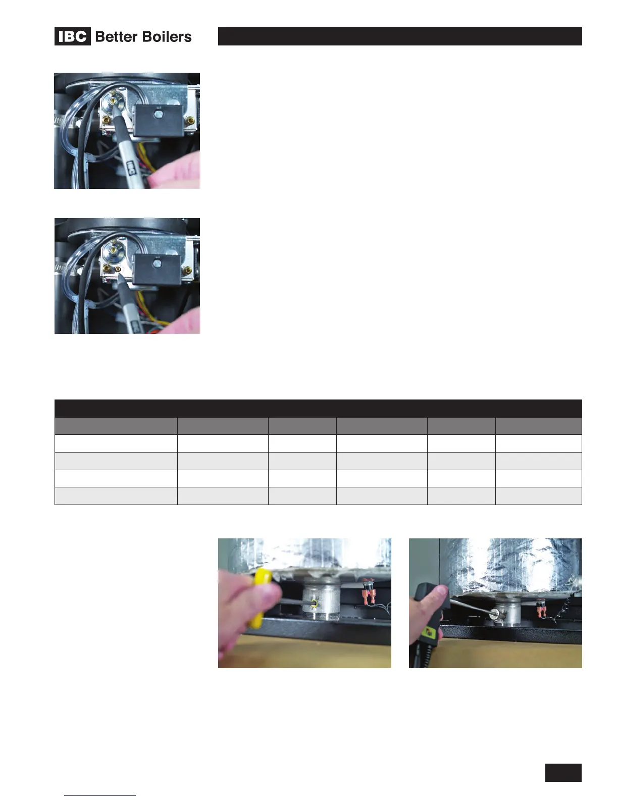
3. With the boiler at maximum output, use a 2 mm hex key to adjust the zero-
offset (see Figure 32, “A”) as required to achieve -0.2 to -0.3” wc. This
adjustment should only be necessary if this screw has been tampered with.
4. With a combustion analyzer probe in the ue gas test port, turn the Gas:Air
Ratio Adjustment screw (see Figure 32, “B”) to achieve the appropriate Table
8 mixture target at High Fire. This screw offers very ne adjustment, and
may require several turns. NOTE: This screw has signicant backlash. When
changing direction of turn, it may take up to a full turn before any change
is indicated on the analyzer reading. Clock the gas meter to conrm full
maximum rating plate input.
5. To conrm or adjust the minimum re level settings, Re-dene the load as
“Manual Control”. Use Heat Output in “Congure Load x” to control the output
as needed.
6. At the minimum ring rate, adjust the zero-offset screw (see Figure 32, “A”)
to obtain the target CO
2
value. It may be necessary to reduce the output in
stages if this adjustment has been tampered with.
7. Turn boiler off by removing the call for heat (use the Heat Load Conguration
screen to turn load to off if no other ready means available); turn OFF gas
supply to boiler, then remove the manometer connections, and turn the
centre-screw in the manifold pressure test port 1 full turn clockwise. Ensure
fully closed, but not over-tightened. Restore gas and soap test for leaks.
Zero-offset adjustment screw
Gas:Air ratio adjustment screw
Insertion of ue gas analyzer probeRemoval of ue gas test port plug
MODEL HIGH FIRE LOW FIRE CO MAX PPM
RANGE TARGET RANGE TARGET
VFC 15-150 (Natural Gas) 8.9 to 9.5% CO
2
9.2% CO
2
7.9 to 8.6% CO
2
8.4% CO
2
< 100
VFC 15-150 (Propane) 10.4 to 10.7% CO
2
10.6% CO
2
9.0 to 9.8% CO
2
9.6% CO
2
< 150
VFC 45-225 (Natural Gas) 8.9 to 9.5% CO
2
9.2% CO
2
7.9 to 8.6% CO
2
8.4% CO
2
< 120
VFC 45-225 (Propane) 10.4 to 10.7% CO
2
10.6% CO
2
9.0 to 9.8% CO
2
9.6% CO
2
< 180
Table 8: Combustion test target ranges - CO
2
/ Maximum CO