be installed ), around the tape guide stan
d,
and
around the tape reel nylon roll.
7. Lower th idl r roller onto the supply r
I.
8. Lower the buffer arm gentl
y.
9.
Pr
ess
the reel power key. The buffer a
Tm
s should
swing down
to
a neutral po ition, apply
in
g tension
to the
pap
er tape.
NOT
E :
Th
e roll of
pap
er tape must be po itioned cen-
trall
y,
or evenl
y,
around the ce
nt
er rollers to
pr
event
ex
c
ess
ive vibration during readin
g.
R
EE
L
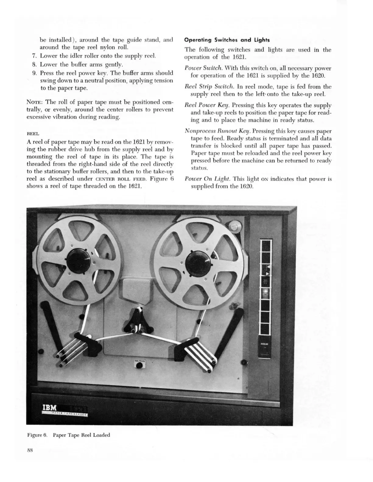
A reel of
pap
er tape may be r ad on the
16
21 b remov-
ing the
rubb
er drive
hub
from the upply reel and by
mounting the re I of tap in
it
s place.
Th
e tap IS
threaded from the
ri
g
ht
-hand s
id
e of
th
e reel direc
tl
y
to
the stationary buffer roller
s,
and then to the tak
e-
up
reel as d
es
cribed under
CE
'
TE
R
ROLL
FEE
D. Figure 6
shows a reel of tape thread d on th
16
2
1.
Figure 6. Paper Tape Reel Loaded
88
Operat
ing Switches
and
Lights
Th
e
fo
llo
wi
ng switche a
nd
li
g
ht
s are used in the
operation of the
16
2
1.
P
owe.,.
Sw
it
ch. With this switch on a
ll
nec
ess
ary power
fo
r opera
ti
on of the
16
21 i ' upplied by the
16
20.
Reel Strip Sw i
tc
h.
In
reel mod
e,
tape is fed from the
supply reel then
to
the left· onto the tak -up ree
l.
Reel P
owe
r Key. Pr
ess
ing this key operate the supply
a
nd
take-up reels to p
os
ition the
pa
per tap for read-
in
g a
nd
to place the machine in ready statu .
on
rJ
rocess Runout Key. Pr
ess
ing this key causes
pap
er
tape to fe d. Ready status i terminated and a
ll
dat
a
tran
fe
r is block d until all paper tape h
as
pa se
d.
Paper tape must be reloaded and the reel power key
pr
essed before the machine can be r turned to read
status.
Po
we
r On L
ig
h
t.
This
li
g
ht
0 r indicat
es
that power i '
supplied from the
16
20.