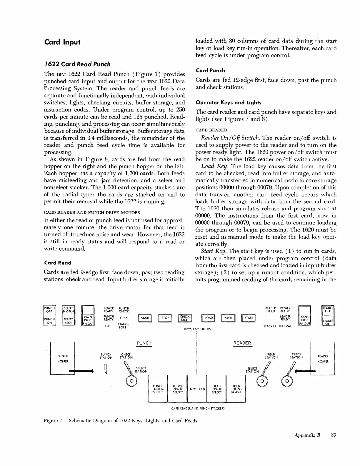
Card Input
1622
Card Read
Punch
The
IBM
1622
Card
Read
Punch
(Figure
7)
provides
punched
card
input
and
output
for
the
IBM
1620
Data
Processing System.
The
reader
and
punch
feeds are
separate
and
functionally independent,
with
individual
switches, lights, checking circuits, buffer storage,
and
instruction codes.
Under
program control,
up
to 250
cards
per
minute
can
be
read
and
125
punched.
Read-
ing, punching,
and
processing can occur Simultaneously
because
of individual buffer storage. Buffer storage
data
is transferred
in
3.4 milliseconds;
the
remainder
of the
reader
and
punch
feed cycle time is available for
processing.
As
shown
in
Figure
8,
cards
are
fed from
the
read
hopper
on
the
right
and
the
punch
hopper
on
the
left.
Each
hopper
has a capacity
of
1,200 cards. Both feeds
have misfeeding
and
jam detection,
and
a select
and
nons elect stacker.
The
1,000-card-capacity stackers
are
of
the
radial
type:
the
cards
are
stacked on
end
to
permit
their
removal while
the
1622 is running.
CARD
READER
AND
PUNCH
DRIVE
MOTORS
If
either
the
read
or
punch
feed is
not
used
for approxi-
mately one minute,
the
drive motor for
that
feed is
turned
off to
reduce
noise
and
wear. However,
the
1622
is still
in
ready
status
and
will respond to a
read
or
write command.
Card
Read
Cards
are
fed
9-edge first, face down,
past
two reading
stations, check
and
read.
Input
buffer storage is initially
POWER
PUNCH
READY
CHECK
PUNCH
CHIP
~
STOP
II
CHECK
READY
RESET
FUSE
TRANS-
loaded
with
80 columns of
card
data
during
the
start
key or
load
key run-in operation. Thereafter,
each
card
feed cycle is
under
program control.
Card Punch
Cards
are
fed
12-edge first, face down,
past
the
punch
and
check stations.
Operator
Keys
and
Lights
The
card
reader
and
card
punch
have
separate
keys
and
lights
(see
Figures 7
and
8).
CARD
READER
Reader
On/OfJ
Switch.
The
reader
on/off
switch is
used to
supply
power
to
the
reader
and
to
turn
on
the
power
ready
light.
The
1620
power
on/off
switch
must
be
on to
make
the
1622
reader
on/off
switch active.
Load
Key.
The
load
key causes
data
from
the
first
card
to
be
checked,
read
into buffer storage,
and
auto-
matically transferred in numerical
mode
to core storage
positions
00000
through
00079.
Upon
completion of this
data
transfer, another
card
feed cycle occurs which
loads buffer storage
with
data
from
the
second card.
The
1620
then
simulates release
and
program
start
at
00000.
The
instructions from
the
first card,
now
in
00000
through
00079, can
be
used
to continue loading
the
program
or
to
begin
processing.
The
1620
must
be
reset
and
in
manual
mode to make
the
load key oper-
ate
correctly.
Start Key.
The
start
key is
used
(1)
to
run
in
cards,
which
are
then
placed
under
program
control
(data
from
the
first
card
is checked
and
loaded
in
input
buffer
storage);
(2)
to
set
up
a
runout
condition,
which
per-
mits
programmed
reading
of
the
cards remaining in
the
READER
POWER
CHECK
READY
LOAD
II
STOP
II
II
START
II
READER
READY
STACKER
THERMAL
PORT
KEYS
AND
LIGHTS
i
PUNCH
I
READER
PUNCH
PUNCH
CHECK
I
READ
CHECK
READER
STATION
STATION STATION
STATION
HOPPER
I
~
HOPPER
~
~mCT
I
SELECT
I
0
ATION
!
STATION P
PUNCH
PUNCH
READ
READ
0 G
NON-
ERROR
NOT
USED
ERROR
NON-
SELECT
SELECT
SELECT
SELECT
CARD
READER
AND
PUNCH
STACKERS
Figure
7. Schematic
Diagram
of 1622 Keys, Lights,
and
Card
Feeds
AppendiX B 89