Chapter 2. Architecture and technical overview 47
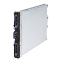
Figure 2-7 Memory DIMM topology for the PS700
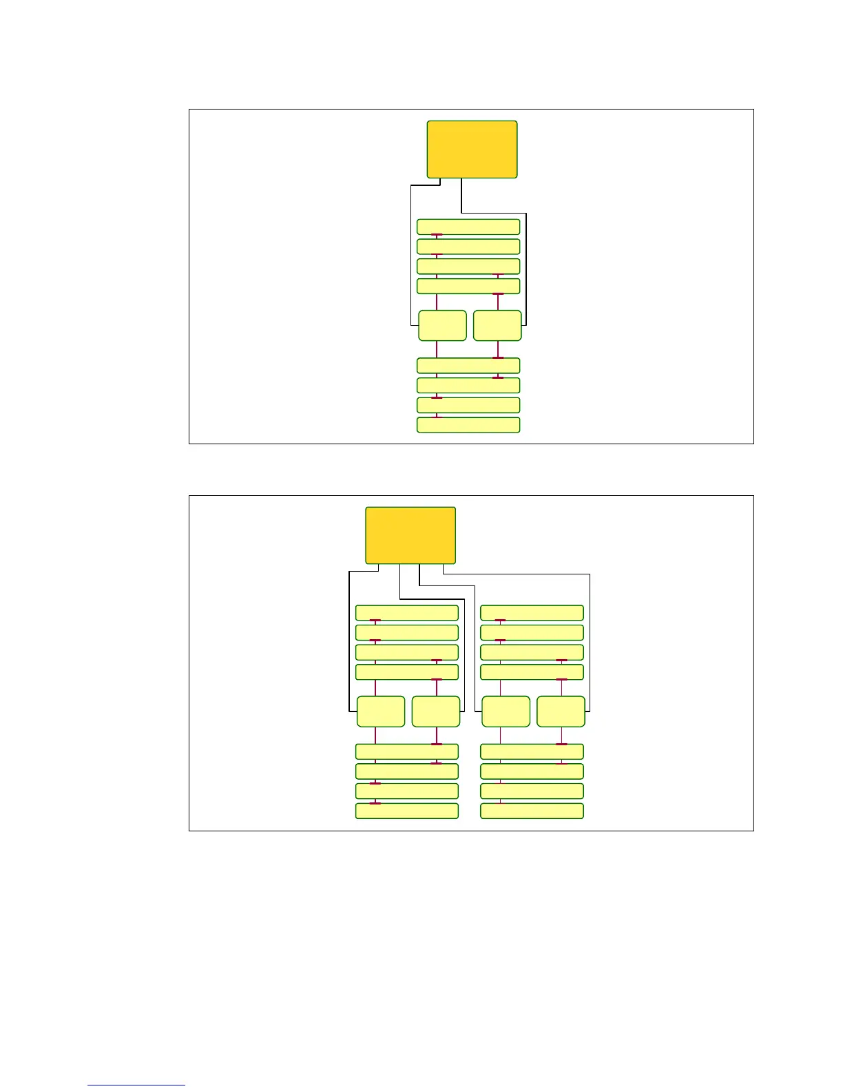
Figure 2-8 Memory DIMM topology for the PS701 and PS702 base blade
There are eight buffered DIMM slots on the PS700, and 16 on the PS701 and PS702 base
blade with an additional 16 slots on the PS702 expansion unit. The PS700 DIMM slots are
numbered P1-C1 through P1-C8 as shown in Figure 2-7. The PS701 and the PS702 base
blade have slots labelled P1-C1 through P1-C16 as shown in Figure 2-8. For the PS702
expansion unit the numbering is the same except for the reference to the second planar
board. The numbering is from P2-C1 through P2-C16.
AA
DIMM P1-C7
DIMM P1-C8
Buffer
DIMM P1-C2
DIMM P1-C1
BB
Buffer
DIMM P1-C6
DIMM P1-C5
DIMM P1-C3
DIMM P1-C4
P7 processor
chip
AA
DIMM P1-C7
DIMM P1-C8
Buffer
DIMM P1-C2
DIMM P1-C1
BB
Buffer
DIMM P1-C6
DIMM P1-C5
DIMM P1-C3
DIMM P1-C4
BB
DIMM P1-C15
DIMM P1-C16
Buffer
DIMM P1-C10
DIMM P1-C9
AA
DIMM P1-C14
DIMM P1-C13
DIMM P1-C11
DIMM P1-C12
P7 processor
chip
Buffer
 Loading...