176 IBM Power 720 and 740 Technical Overview and Introduction
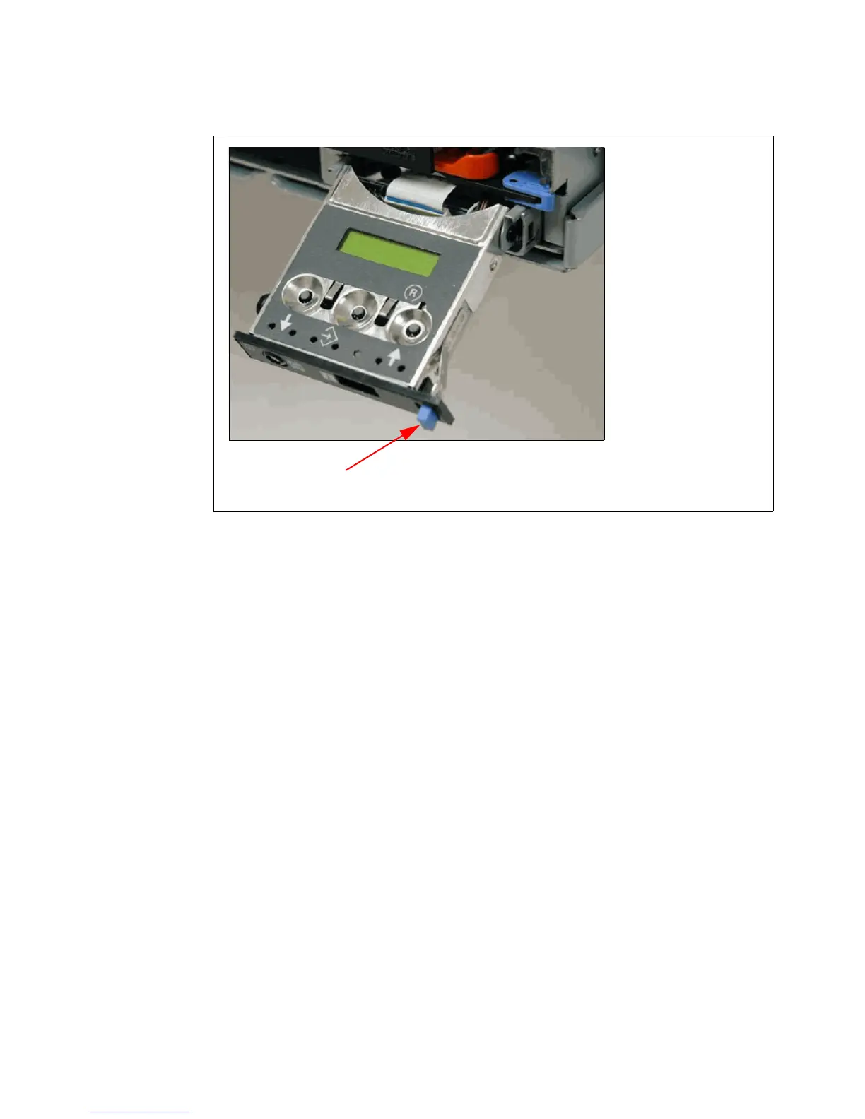
Figure 4-5 shows that the operator panel on a Power 720 and Power 740 is pulled out.
Figure 4-5 Operator panel is pulled out from the chassis
Several of the operator panel features include the following items:
A 2 x 16 character LCD display
Reset, enter, power On/Off, increment, and decrement buttons
Amber System Information/Attention, green Power LED
Blue Enclosure Identify LED on the Power 720 and Power 740
Altitude sensor
USB Port
Speaker/Beeper
The following functions are available through the operator panel:
Error Information
Generate dump
View machine type, model, and serial number
Limited set of repair functions
Operating system service menu
The system diagnostics consist of IBM i service tools, stand-alone diagnostics that are loaded
from the DVD drive, and online diagnostics (available in AIX).
Online diagnostics, when installed, are a part of the AIX or IBM i operating system on the disk
or server. They can be booted in single-user mode (service mode), run in maintenance mode,
or run concurrently (concurrent mode) with other applications. They have access to the AIX
error log and the AIX configuration data. IBM i has a service tools problem log, IBM i history
log (QHST), and IBM i problem log.
Release Lever
(slide left to release operator panel and pull out from chassis)

 Loading...