Chapter 2. Architecture and technical overview 43
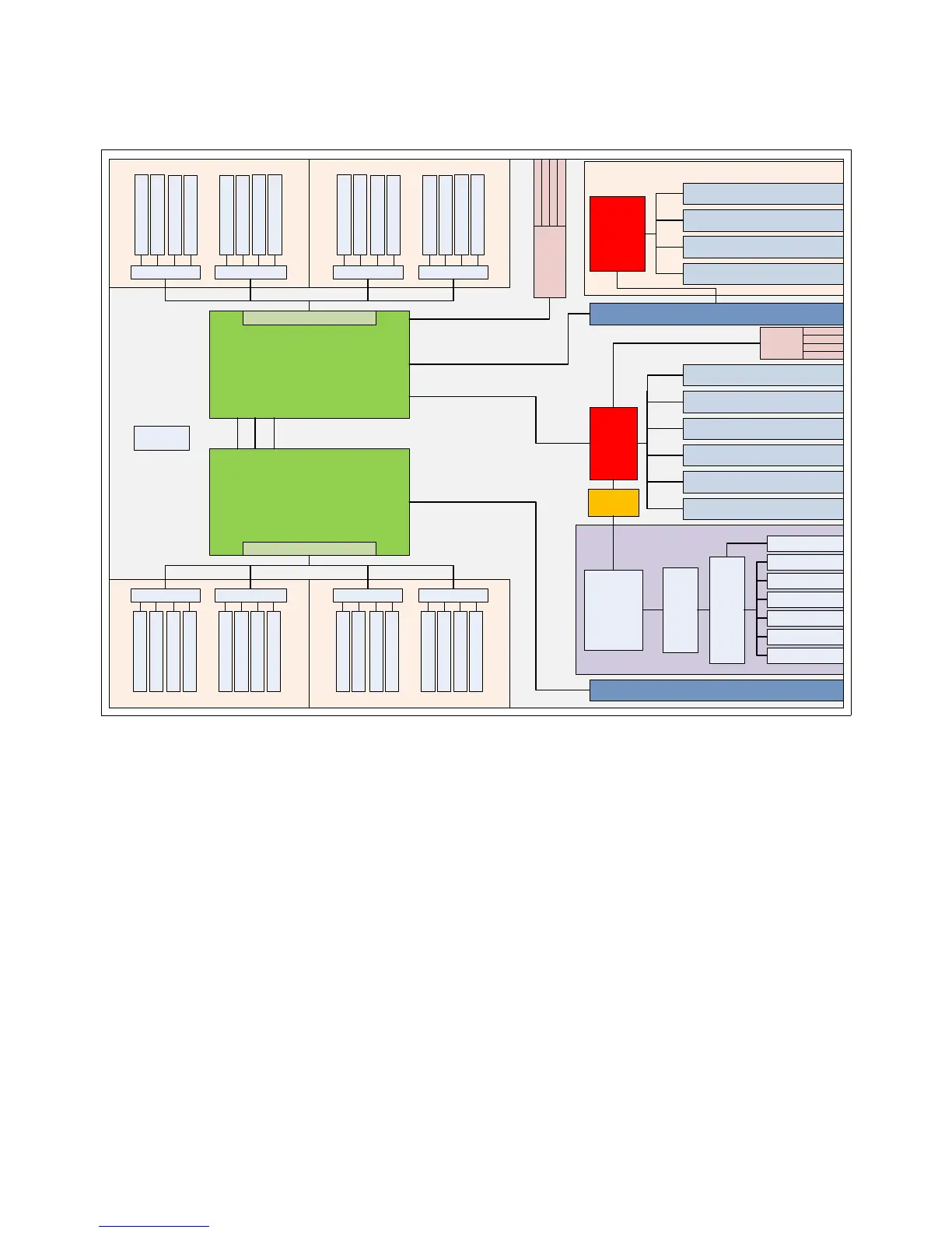
POWER7+ Chip 2
6 or 8 cores
POWER7+ Chip 1
6 or 8 cores
P7-IOC
Buffer Buffer
DIMM #1
DIMM #3
DIMM #6
DIMM #8
Memory Card #1 Memory Card #2
Memory Card #3 Memory Card #4
PCIe Gen2 x8 (Short, LP) – SLOT #1
PCIe Gen2 x8 (Short, LP) – SLOT #2
PCIe Gen2 x8 (Short, LP) – SLOT #3
PCIe Gen2 x8 (Short, LP) – SLOT #4
GX++ SLOT #1
GX++ SLOT #2
PCIe Gen2 x8 (FH/HL) SLOT #2
PCIe Gen2 x8 (FH/HL) SLOT #3
PCIe Gen2 x8 (FH/HL) SLOT #4
PCIe Gen2 x8 (FH/HL) SLOT #5
PCIe Gen2 x8 (FH/HL) SLOT #1
P7-IOC
(Optional
Expansion)
Optional PCIe Gen2 Riser
PCIe Gen2 x4 (FH/HL) SLOT #6
DIMM #5
DIMM #7
DIMM #2
DIMM #4
Buffer Buffer
DIMM #1
DIMM #3
DIMM #6
DIMM #8
DIMM #5
DIMM #7
DIMM #2
DIMM #4
Buffer BufferBuffer Buffer
DIMM #1
DIMM #3
DIMM #6
DIMM #8
DIMM #5
DIMM #7
DIMM #2
DIMM #4
DIMM #1
DIMM #3
DIMM #6
DIMM #8
DIMM #5
DIMM #7
DIMM #2
DIMM #4
TPMD
Memory Controller
Memory Controller
SAS
Controller
RAIDs 0,1,10
Optional RAID 5 & 6
Expansion Card
DASD & Media Backplane
HDD1
HDD2
HDD3
HDD4
HDD5
HDD6
DVD
USB #1
USB #2
USB #3
USB #4
USB
Controller
2 System Ports
2 HMC Ports
2 SPCN Ports
VPD Chip
Service Processor
PCIe
Switch
68.2 GB/s
68.2 GB/s
19.7 GB/s
19.7 GB/s
19.7 GB/s
 Loading...