54 IBM Power 720 and 740 Technical Overview and Introduction
Table 2-6 shows the maximum memory that is supported on the Power 740.
Table 2-6 Power 740 maximum memory
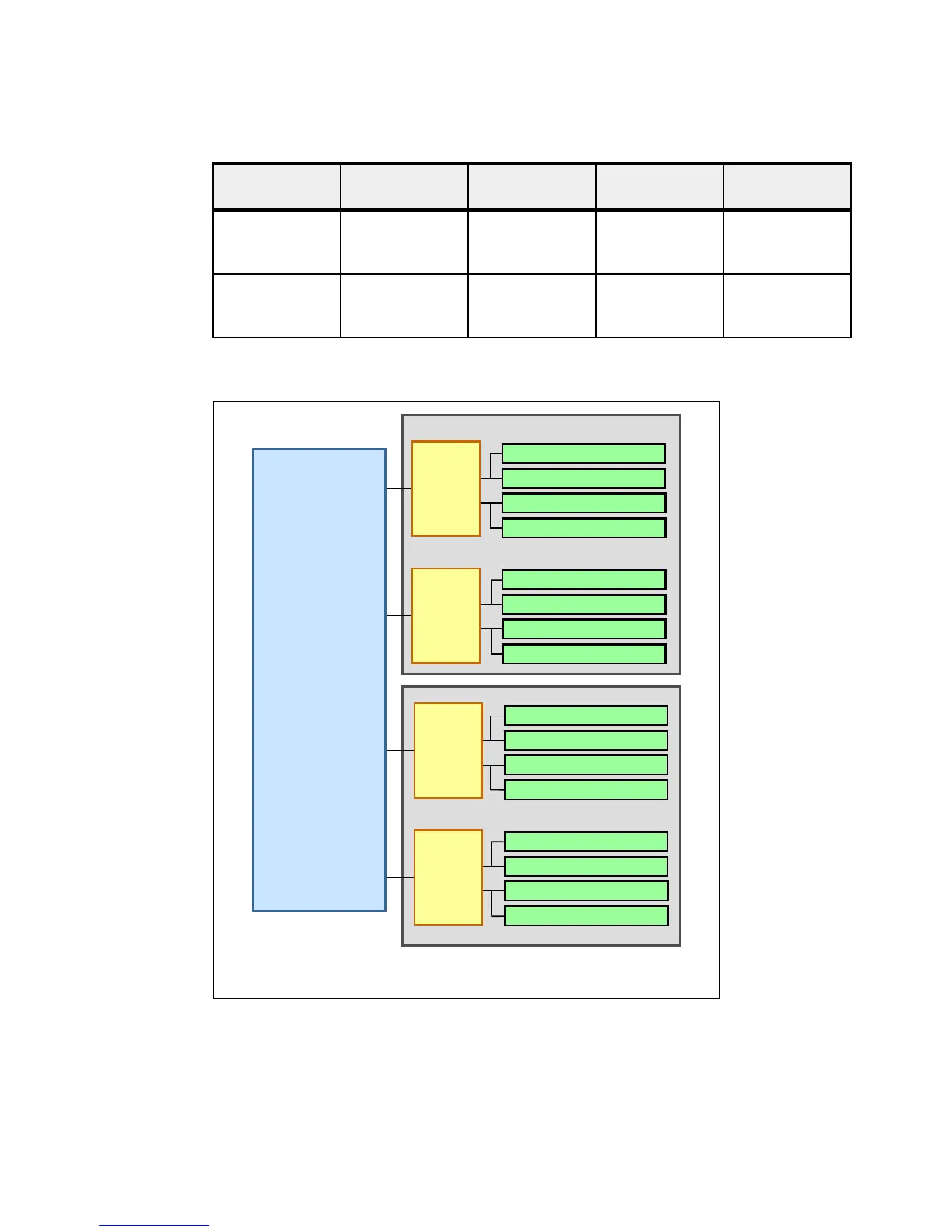
Figure 2-8 shows the logical memory DIMM topology for the POWER7 processor card.
Figure 2-8 Memory DIMM topology for the Power 720 or Power 740
Processor
cores
One memory
riser card
Two memory
riser cards
Three memory
riser cards
Four memory
riser cards
1 x 4-core
1 x 6-core
1 x 8-core
256 GB 512 GB Not available Not available
2 x 4-core
2 x 6-core
2 x 8-core
256 GB 512 GB 768 GB 1024 GB
POWER7+
SCM
MC0
Channel D
MC0
Channel C
MC0
Channel B
MC0
Channel A
MC: Memory Controller
BC: Memory Buffer
Memory Card #2
DDR3 RDIMM Slot 2
DDR3 RDIMM Slot 1
DDR3 RDIMM Slot 8
DDR3 RDIMM Slot 7
BC-B
DDR3 RDIMM Slot 4
DDR3 RDIMM Slot 3
DDR3 RDIMM Slot 6
DDR3 RDIMM Slot 5
BC-A
Memory Card #1
DDR3 RDIMM Slot 4
DDR3 RDIMM Slot 3
DDR3 RDIMM Slot 6
DDR3 RDIMM Slot 5
BC-A
DDR3 RDIMM Slot 2
DDR3 RDIMM Slot 1
DDR3 RDIMM Slot 8
DDR3 RDIMM Slot 7
BC-B
 Loading...