System-board connectors
Blade server components attach to the connectors on the system board.
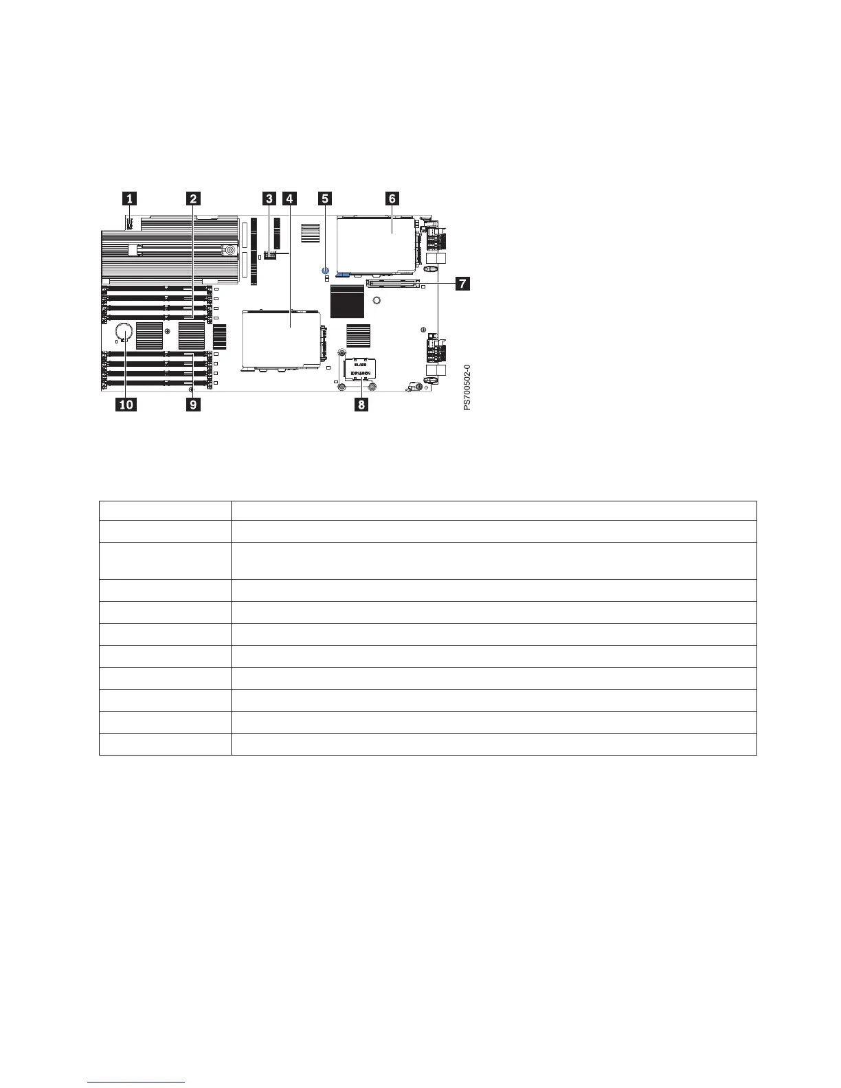
Figure 2 shows the connectors on the base unit system board in the blade server.
Table 2 shows connector descriptions.
Table 2. PS700 connectors
Callout PS700 blade server connectors
1 Operator panel connector
2 DIMM 1-4 connectors (See Figure 3 on page 16 for individual connectors.) Expansion unit
(SMP) connector
3 Management card connector (P1-C9)
4 SAS hard disk drive connector (P1-D2)
5 Light Path Blue Button
6 SAS hard disk drive (P1-C10)
7 CIOv (1Xe) expansion card connector (P1-C11)
8 High-Speed (CFFh) expansion card connector (P1-C12)
9 DIMM 5-8 connectors (See Figure 3 on page 16 for individual connectors.)
10 3V lithium battery connector (P1-E1)
Figure 3 on page 16 shows individual DIMM connectors.
Figure 2. PS700 system-board connectors
Chapter 2. Power, controls, indicators, and connectors 15
 Loading...


