System-board LEDs
Use the illustration of the LEDs on the system board to identify a light emitting diode (LED).
Remove the blade server from the BladeCenter unit, open the cover, press the blue button to see any
error LEDs that were turned on during error processing, and use Figure 4 to identify the failing
component.
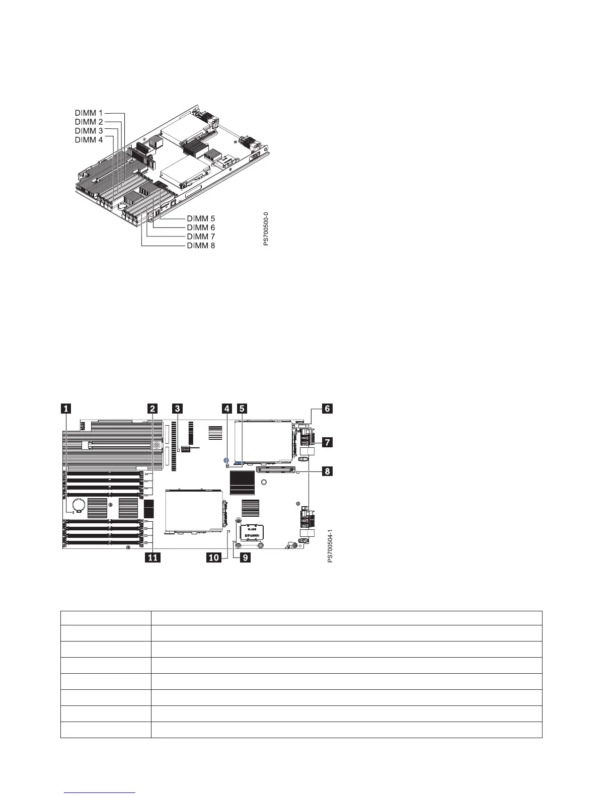
Figure 4 shows the locations of LEDs on the system board.
Table 3 shows LED descriptions.
Table 3. PS700 LEDs
Callout Base unit LEDs
1 3V lithium battery LED
2 DIMM 1-4 LEDs
3 Management card LED
4 Light path power LED
5 System board LED
6 HDD1 LED
7 Interposer LED
Figure 3. DIMM connectors. Base unit connectors
Figure 4. LED locations on the system board of the PS700 blade server
16 Power Systems: Installation and User's Guide for the IBM Power PS700 (8406-70Y)