EasyManuals Logo

IBM Power System 9009-42A User Manual

IBM Power System 9009-42A
170 pages
To Next Page IconTo Next Page
To Previous Page IconTo Previous Page
Page #139 background imageLoading...
Page #139 background image
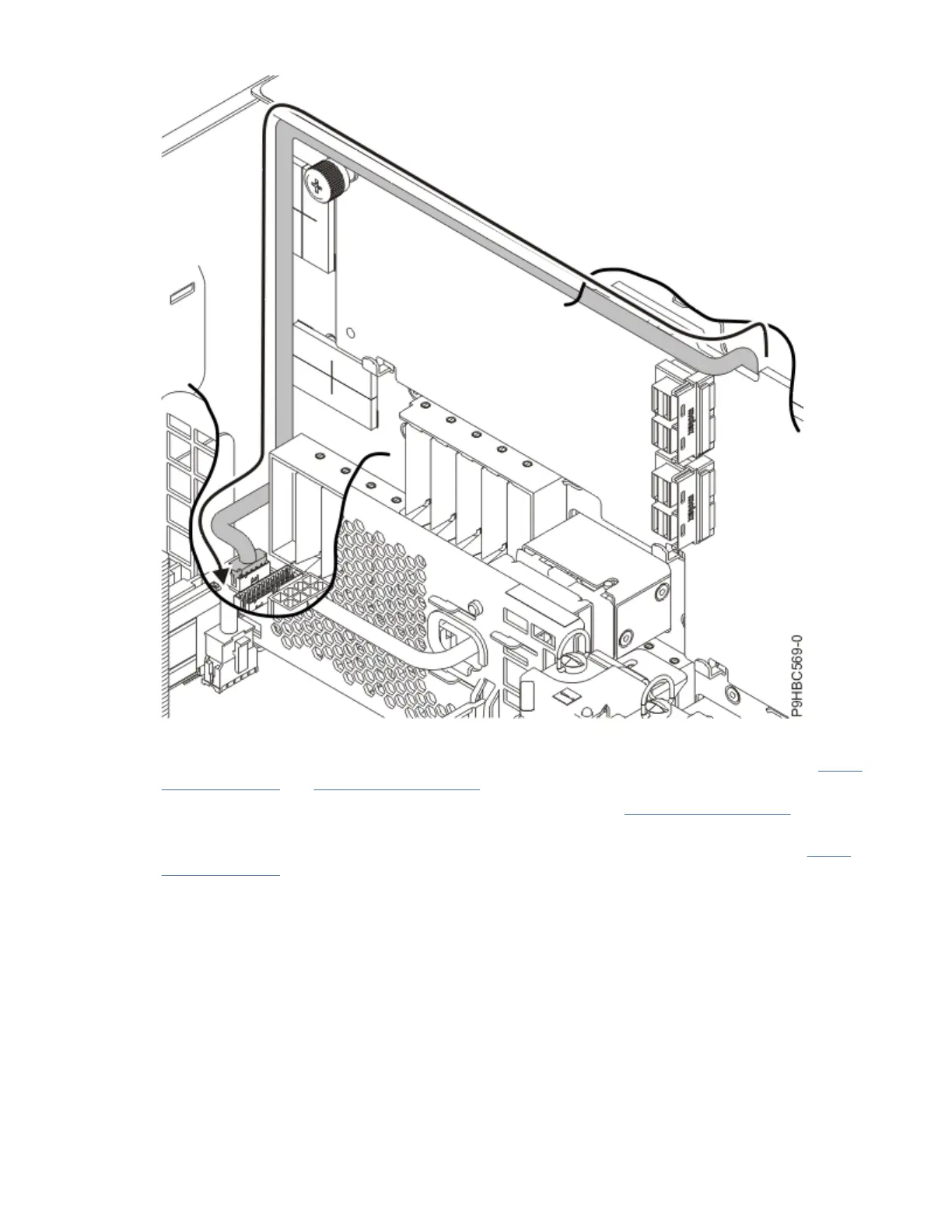
Figure 120. Control panel display cable path for a rack-mounted system
4. For the stand-alone system, insert the control panel display cable into the system as shown in Figure
121 on page 126 and Figure 122 on page 127.
a) Pull any cable slack inside the system in the direction shown in Figure 122 on page 127 to prevent
the cable from interfering with the fan.
5. Secure the control panel display housing to the system using the two screws (A) as shown in Figure
121 on page 126.
Control panel cables for the 9009-41A, 9009-42A, or 9223-42H
125

Questions and Answers:

Question and Answer IconNeed help?

Do you have a question about the IBM Power System 9009-42A and is the answer not in the manual?

IBM Power System 9009-42A Specifications

General IconGeneral
BrandIBM
ModelPower System 9009-42A
CategoryServer
LanguageEnglish

Related product manuals