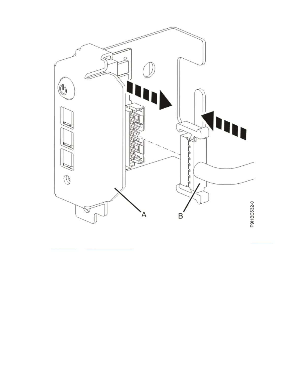
Figure 72. Connecting the control panel and cable for a stand-alone system
3. For a rack-mounted system, insert the control panel and cable into the system as shown in Figure 73
on page 77 and Figure 74 on page 78.
If needed, label and remove two or three leftmost drives, to allow you to route the cable along the
side of the chassis. Pass the cable through the channel along the side of the chassis, being careful not
to catch the cable on any components as you insert it.
76
Power Systems: Power Systems: Control panel
 Loading...


