2030 LCD panel, LCD cable assembly,
wireless LAN antenna assembly,
hinges, and LCD cover
For access, remove these FRUs in order:
v “1010 Battery pack” on page 68
v “1020 Ultrabay Enhanced device” on page 69
v “1030 Hard disk drive” on page 70
v “1050 Keyboard” on page 73
v “1070 Modem daughter card (MDC/MDC-2)” on page 78
v “1080 Bluetooth/Modem daughter card
(BMDC/BMDC-2)” on page 80
v “1090 Keyboard bezel” on page 82
v “1100 Mini PCI adapter” on page 86
v “1170 Ultrabay Enhanced shield kit” on page 100
v “1180 LCD assembly” on page 107
v “2010 LCD front bezel” on page 121
v “2020 Inverter card” on page 123
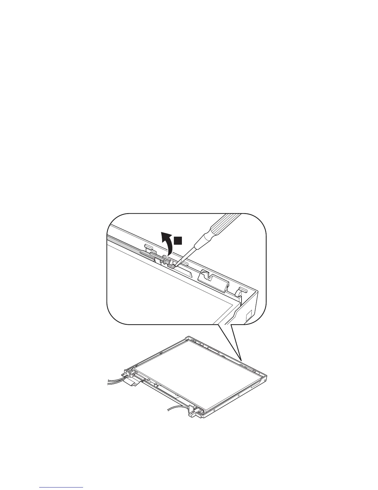
Before removing the LCD panel, remove the left latch first.
In step 1, unlatch the latch bar as in this figure.
1
(continued)
Removing and replacing a FRU
124 R50/R50p, R51 Series
 Loading...