Chapter 1. Planning
Planning involves considering the physical conguration, the initial data conguration, and the necessary
software prerequisites to include your system in your storage area network.
System overview
The SAN Volume Controller family of systems combines software and hardware into a comprehensive,
modular appliance that provides symmetric virtualization.
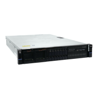
SAN Volume Controller SA2 and SV2 node features
The system has the following features.
• A 19-inch rack-mounted node
• Two 8-core (SA2) or 16-core (SV2) processors
• 128 GB base memory per canister (256 GB per node). Optionally, by adding 32 GB memory modules,
each node can support up to 768 GB (SA2) or 1,443 GB (SV2) of memory.
• Support for up to three optional host adapters, including:
– 4-port 16 Gbps and 4-port 32 Gbps Fibre Channel over NVMe adapters
– 2-port 25 Gbps iSCSI/iWARP/NVMe over Ethernet adapters
– 2-port 25 Gbps iSCSI/RoCE/NVMe over Ethernet adapters
• Dual redundant power supplies
• A dedicated technician port to initialize or service the system
Physical conguration planning of the system
Before you install the system, plan the physical conguration and the initial data conguration. Certain
physical site specications must be met before you can set up your system. This activity includes verifying
that adequate space is available, and that requirements for power and environmental conditions are met.
Procedure
1. Use the hardware location chart to record the physical conguration of your system.
2. Use the cable connection tables to plan and record all connections between your system units.
3. Use the conguration data tables to record the data required before the initial installation.
Results
Once the physical conguration is complete, plan for the physical installation.
Completing the hardware location chart
Planning for the physical location of the system hardware includes documenting the rack locations of the
enclosures and other devices. To determine the rack location, review the requirements and specication
of each device.
The hardware location chart represents the rack into which the enclosures are installed. Each row of the
chart represents one Electronic Industries Alliance (EIA) 19-inch wide by 1.75-inch tall rack space or
unit, each of which is commonly referred to as 1U of the rack. As you design your rack for your system,
use Table 1 on page 2
to record the physical conguration of the enclosures and other devices in your
system.
©
Copyright IBM Corp. 2020 1