21
Installation
Installation
The installation of the device can be carried out by a person who knows the manual
thoroughly and has appropriatehydraulic and electrical qualications. The device can
operate in installations in which pure water is pumped without the content of iron or
iron oxides. Operation of the device with dirty water will lead to its failure.
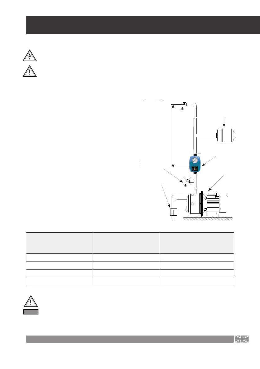
The device must be installed on the pump discharge side in a vertical position between
the pump and the rst water consumer (g. 1).
Switching on pressure
[bar]
Max. height between
PC-59 controoler and
the hieghest tap [m]
The minimum pressure the
pump must generate to achieve
switch-o pressure [bar]
0,8 8 2
1,2 12 2,2
1,5 15 2,5
2,2 22 3,2
When installing, pay attention to the direction of
water ow through the device. An arrow is stamped
on the housing to show the correct direction of ow.
If the device has work in an installation where the
pressure is over 10 bar, install a pressure reducer
upstream of the device to reduce the pressure in
the device. Connections of the PC-59 machine with
the pipes are best sealed with Teon tape. Max he-
ight of the water column above depends on the
setting of the switch-on pressure and cannot be hi-
gher than the head of the water column correspon-
ding to the switch-on pressure. The cut-in pressure
should also be selected depending on the pump’s
capabilities. If the PC-59 is to function properly, the
pump must be able to generate a pressure at le-
ast 1 bar higher than the switch-on pressure (the
minimum dierence between the switch-on and
switch-o pressure is 1 bar).
Table no.1
Due to possible ow disturbances between the pump and the device, no check
valves should be installed between these devices.
Attention! The device must not be inuenced by an external, strong magnetic eld.
Any magnets should be at least 25 cm away from the device.
Fig. 1.
rurami
wy
yć wyższa
ć ciśnienie
NACZYNIE
PRZEPONOWE
WYŁĄCZNIK PC
POMPA
ZAWÓR
ZWROTNY
WNY
AŻ KRANU
MONTAŻ KRANU
ANLAMYSKAM
OKOSYW ĆŚ
PA T ZRT ALEBA
JEŻINOP
CORRECT
TAP ASSEMBLY
INCORRECT
FAP INSTALLATION
Diaphragmatic
Vessel
VALVE
AGILE
PUMP
PC CONTROLLER
MAXIMUM HEIGHT
ATTENTION