1. CONTROLLER MANUAL
1.1 GENERAL CHARACTERISTICS
− Digital microprocessor power factor controller
− TTL-RS232 serial interface for set-up and automatic testing via PC (Personal Com-
puter)
− Internal temperature sensor
− Advanced functions for capacitor current overload measurement, average weekly
power factor, maximum value logging
− 2 relays programmable as alarm and/or fan control
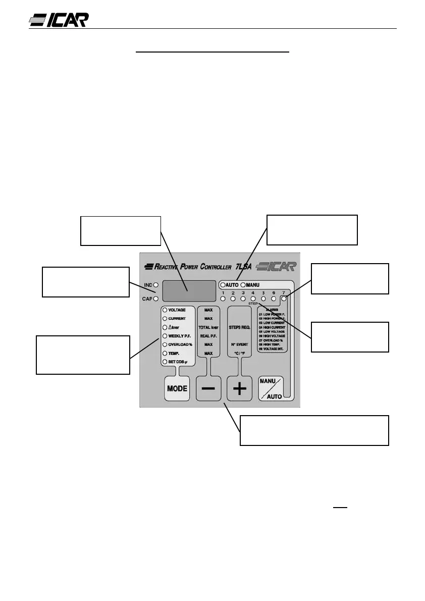
1.2 FRONT PANEL
28
3 digit 7-segment
LED display
LED indicating type
of load detected
4-membrane key keypad access
the controller functions
LED indication of
measurement on the
display
LED indication of
steps enabled
LED indication of
alarms (if preset)
LED indication of
operation selected
1.3 INSTALLATION
Install the controller according to wiring diagrams given on page 29.
The CT (Current Transformer) must be connected to the free phase, i.e. not on phases
used to supply the unit, as indicated in the wiring diagrams.
The controller automatically recognizes the CT current flow. In case of co-generation sys-
tems, disable this function (refer to “Advanced menu” section 1.18 “ADVANCED MENU
SETTINGS”) and connect the CT correctly.
The CT secondary must be earthed/grounded.