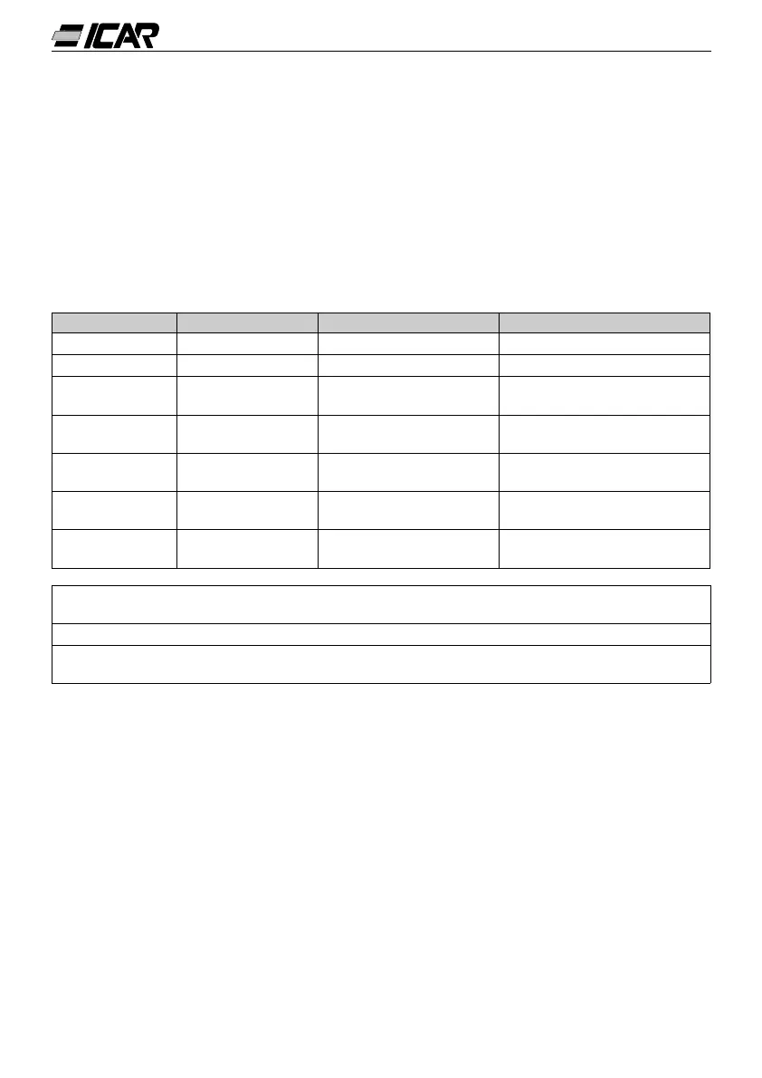
34
LED FUNCTION BY PRESSING - BY PRESSING +
VOLTAGE RMS voltage MAX voltage value
CURRENT RMS current MAX current value
?kvar
kvar required to
reach set-point
Skvar
(system kvar)
Steps (kvar) required to
reach set-point
WEEKLY P.F.
Average weekly
power factor u
Real power factor
OVERLOAD %
Thd I %
capacitors v
MAX overload value Overload event counter
TEMP.
Electric panel
Temperature w
MAX temperature value Unit of meaure °C or °F
SET COSf Required COSf
Decrease SET COSf
value
Increase SET COSf value
u
This PF (Power Factor) value is determined by active and reactive energy meters of
the last 7 days. It is referred to positive energy quadrants only.
v
Overload current (Thd I %) caused by harmonic voltage at the capacitor terminals.
w
Caution! The temperature measurement is considered valid after a period of 20-30
minutes after power up.
1.13 MAXIMUM VALUE CLEARING
The maximum values of Voltage, Current, Overload and Temperature along with average
weekly power factor can be cleared by simultaneously pressing the + and - keys for 3 sec-
onds. Once clearing is complete, the display views CLr.
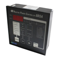
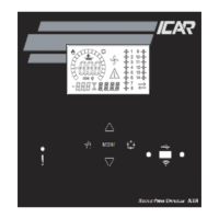
1.14 OPERATING MODE
The AUTO and MANU LED’s indicate the automatic or manual operating mode.
To change mode, press the MANU/AUTO key for at least 1 second.
When the SET COSf LED is lit up, no mode change is possible.
The operating mode remains stored even if power is removed.
1.12 DISPLAY OF MEASUREMENTS AND REQUIRED COSf SETTING
Normally, the display shows the cosf of the system together with the IND and CAP
LED’s. The flashing decimal point indicates the negative sign (inverse energy flow).
By pressing the MODE key, the V, A, ?kvar, etc. LEDs are switched on one after another
and the relative measurement of each is shown.
An optional function is available for each LED and indicated on the front panel, which can
be displayed by pressing the + and - keys (the LED flashes quickly thereafter).
When the SET COSf LED lights up, the set-point of the required cosf can be pro-
grammed; the + and - keys increase or decrease the value respectively. The set cosf can
be adjusted between 0.80 IND and 0.80 CAP.
The following table summarises all the available measurements.