8
Electrical Installation Instruction
Please read the entire section before beginning the electrical installation of the Ice Qube TMS. Ice Qube air
conditioners have been designed for easy electrical power connection at one specific location on the enclosure side
of the Ice Qube TMS. Each Ice Qube TMS been designed to operate at a range of voltages and frequencies. See unit
label(s) for correct voltage and frequency for your model(s).
••WARNING: ELECTRICAL SHOCK AND EXPLOSION HAZARD••
Electrical connections should only be completed by a qualified technician. Compliance with all
safety and electrical codes are required. Contact local authority having jurisdiction as required. Do
not connect while the circuit is energized. Turn off circuit breaker and install lock out. The area is
to be free of ignitable concentration of gases.
Pre-Installation Checks
1. Check the air conditioner model label or specification for power requirements.
2. Check the designated air conditioner power supply for adequate and proper electrical power requirements.
3. Check that wire routing to the terminal box will not interfere with or become damaged by other
components.
Electrical Installation
1. Check that the air conditioner designated power supply is de-energized and locked out.
2. Locate terminal box on enclosure side of air conditioner.
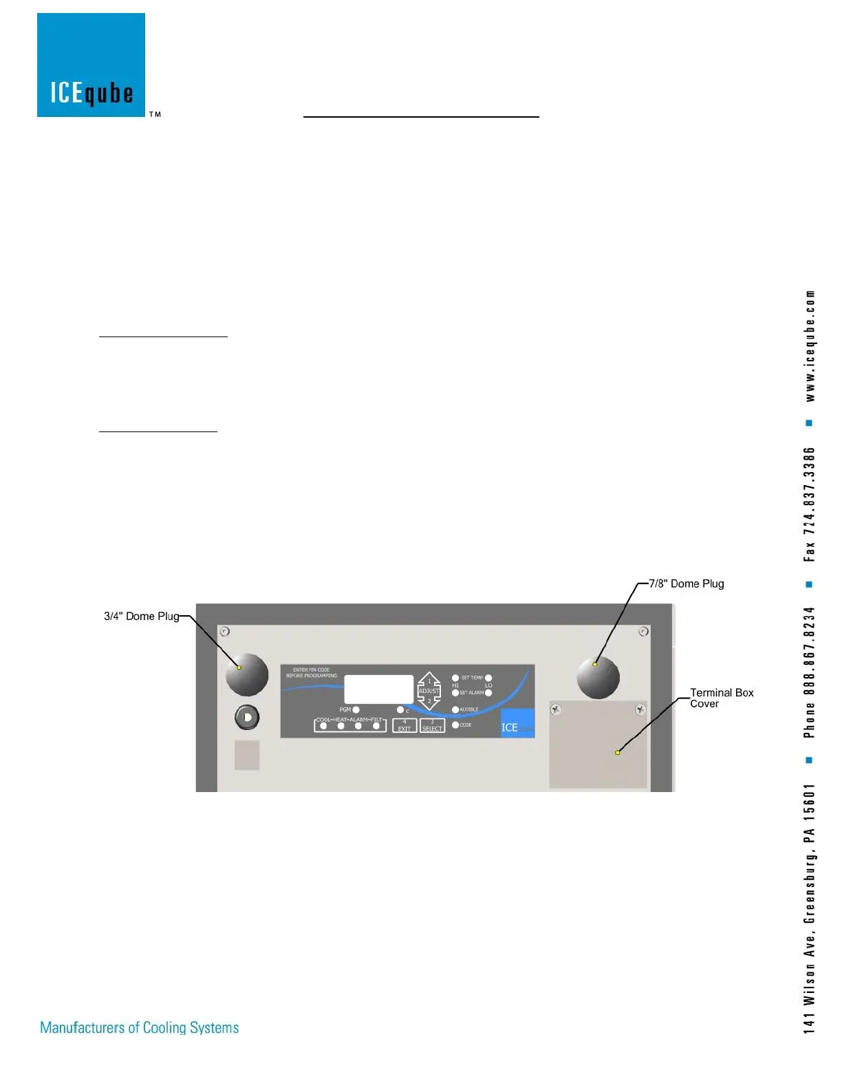
3. Remove the (2) terminal box cover screws and remove the cover. (See Figure 3: Terminal Cover)
4. The terminal block will be used for power. (See Figure 4: Terminal Block)
5. Remove Dome Plug and route power cable through the 0.875” (22.23mm) hole. Recommended conductor
size is 14AWG. Use an approved strain relief to secure wires. (See Figure 3: Terminal Cover)
6. Connect from left to right, Line 1, Line 2 and Ground. (See Figure 5: Power Terminal Block)
7. Once power is securely connected, install terminal box cover, using the (2) screws.
Figure 3: Terminal Cover