7
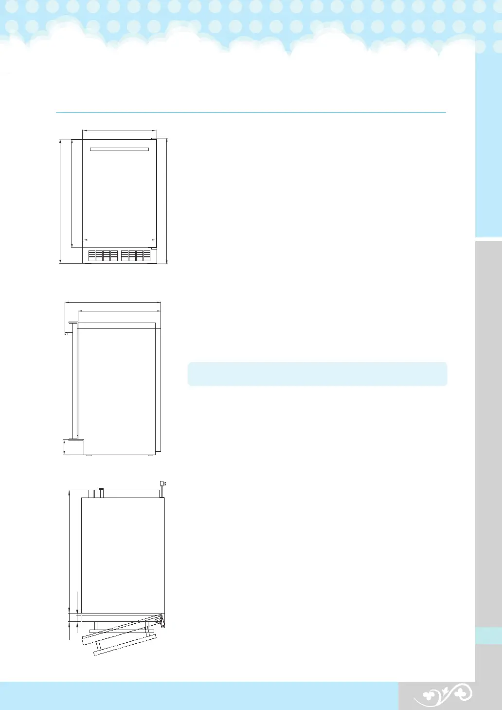
3. Installation specifications
Fig. 1 Front View
Fig. 2 Side View
Fig. 3 Top View
Space requirements for installation
When moving the ice maker, check whether the prepared
opening dimensions,electric rating, and piping position are
correct.
Refer to the installation specifications and drawings shown
on pages 9 and 10.
Figures 4, 5, 6 and 7 show the entire dimensions of the product.
This product is a gravity drain pipe model that requires a
drain pipe to run from the exhaust hole at the back
of the product to appropriate drain pipe.
The optional drain pump to be installed an raised water
to a drainage point such as a neighboring sink.
Refer to the specifications shown on pages 9 and 10.
Important Information :
If the ice maker is installed at
a corner, the lever may be attached to a wall or the front side
of a cabinet, thereby limiting the opening of the door.
The bottom of the ice maker should be leveled.
When moving the product using a hand truck or dolly,
place the dolly at the side of the product and shut or fix
the door tightly to avoid possible opening during movement.
The finished bottom should be protected with a suitable material
to avoid possible damage when moving the product
Important Information : The provisions of the National
Electric Code as well as any local laws and instructions
should be observed when installing the product.
Notification
857
380
752
850
376
538
98
625
538
37
27.8