Keyboard basics
1. Go to the main menu, press the Inc button or the Stop/Batt type button to go down, and press the
Dec button to go up: press the Start/Enter button to enter a sub-menu.
2. In a sub-menu, press Start/Enter to blink the chosen item, and then alter the value with Inc or Dec.
With nothing blinking you can go to the sub-menu below with Inc and above with Dec. Press
Stop/Batt type to go back to the previous screen.
3. In some sub-menus, press and hold Start/Enter for more than 3 seconds to start the process, such as
starting charging or discharging.
4. During the charging/discharging process you can terminate the process at any time by pressing
Stop/Batt type and check the attached information with IncorDec. Press Start/Enter to go back to
the main information screen.
5. During the discharge process, press Start/Enter to alter the discharge current. When the discharge
current blinks, press Inc to increase it or Dec to decrease it, then press Start/Enter to confirm the
change.
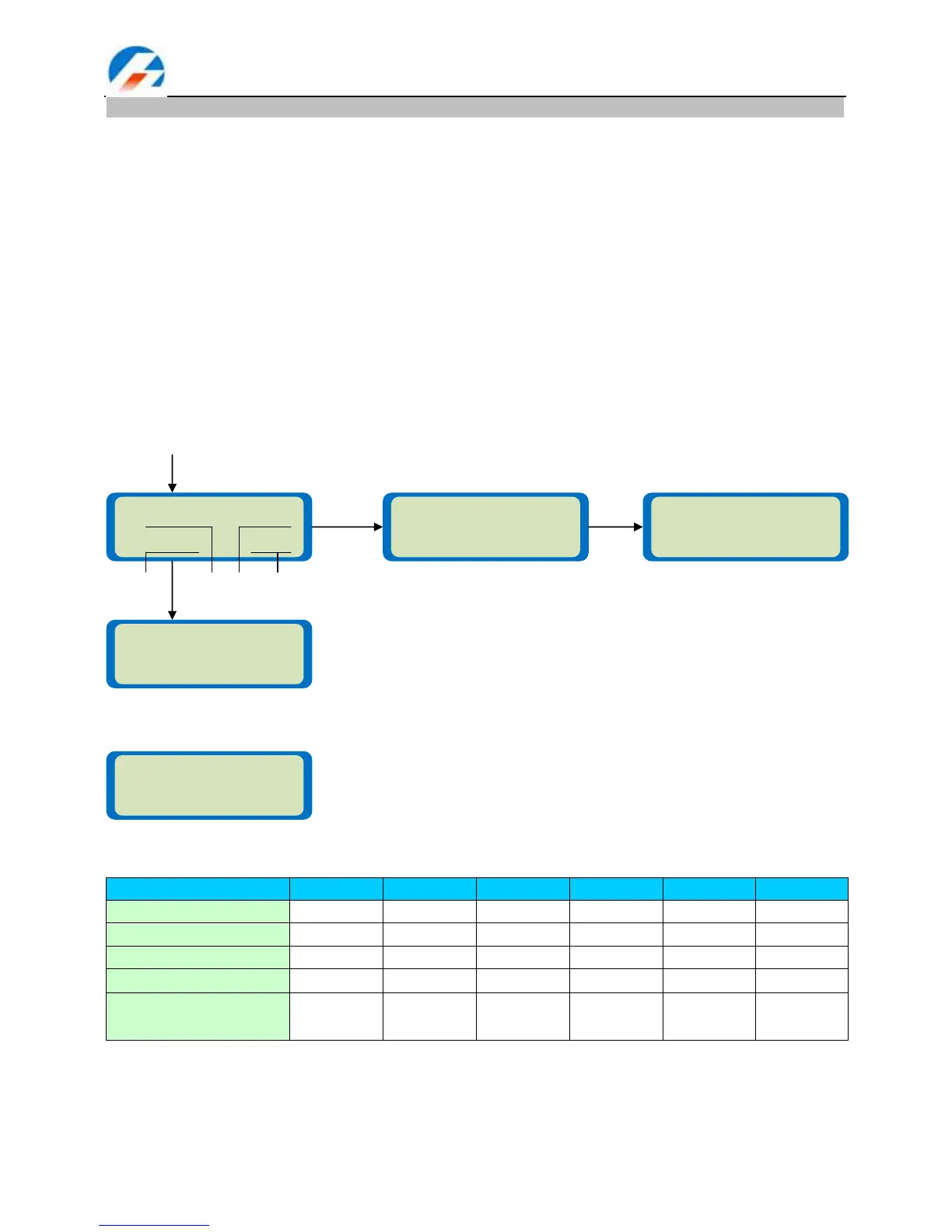
6. Press Stop/Batt type for more than 3 seconds to start the display of the active test information as per
the following diagram.
Present testing information:
7. Reset to Defaults function. Press Stop/Batt type and Start/Enter together for more than 3 seconds to
obtain this display:
Standard battery parameters
NOTE: Be very careful to choose the correct voltage for different types of battery otherwise you may cause
damage to the batteries. Incorrect settings could cause the cells to vent, burn or explode leading to injury or
loss of property.
In the parameter setting chapter that follows the screen diagram on the left shows the system‘s default
setting.